18 VAV-SVX07F-EN
Wiring Installation
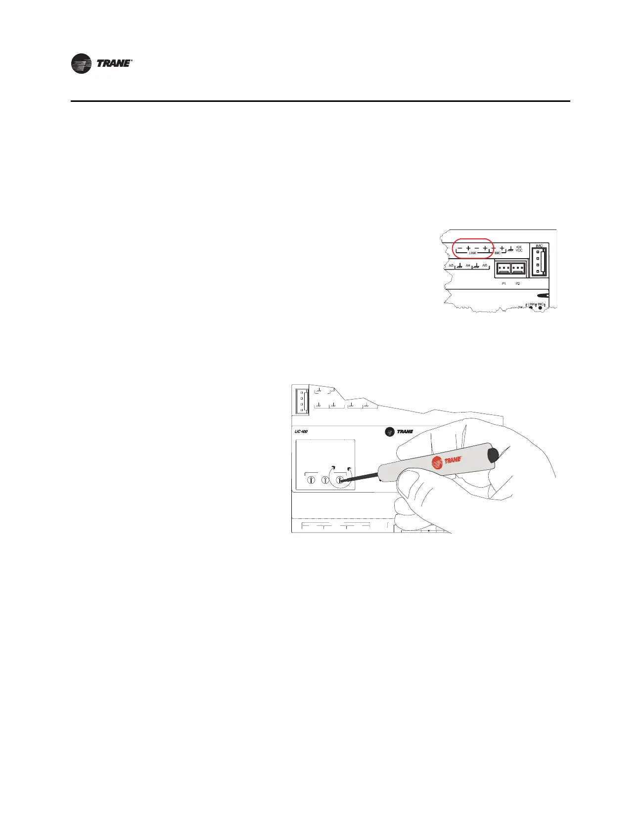
Figure 1. BACnet MS/TP Link Wiring
BI LINK IMC
+
VDC
AIAIAI AI AI
PP
TX
RX
LINK IM
SERVI
SERVICE TOOL
IM
BI LINK IMC
+
VDC
AIAIAI AI AI
PP
TX
RX
LINK IM
SERVI
SERVICE TOOL
IM
BI LINK IMC
+
VDC
AIAIAI AI AI
PP
TX
RX
LINK IM
SERVI
SERVICE TOOL
IM
+
+
BI LINK IMC
+
VDC
AIAIAI AI AI
PP
TX
RX
LINK IM
SERVI
SERVICE TOOL
IM
+
BI LINK IMC
+
VDC
AIAIAI AI AI
PP
TX
RX
LINK IM
SERVI
SERVICE TOOL
IM
+
Tracer SC UC400 UC400 UC400
Zone
Sensor
Zone
Sensor
Zone
Sensor
Trane BACnet terminator
Zone sensor
communications
jack wiring
Wiring Best Practices
To ensure proper network communication, follow the recommended wiring and best practices
below when installing communication wire:
• All wiring must comply with the National Electrical Co
de™ (NEC) and local codes.
• Ensure that 24 Vac power supplies are consistent in regards to
grounding. Avoid sharing 24 Vac
between controllers.
• Avoid over tightening cable ties and other forms of cable wraps. This can damage the wires
inside the cable.
• Do
not run communication cable alongside or in the same conduit as 24 Vac power. This
in
cludes
the conductors running from TRIAC-type inputs.
• In open plenums, avoid running wire n
ear lighting ballasts, especially those using 277 Vac.
• Use same communication wire type, without terminators, for the zone senso
r communication
stubs from the UC400 controller IMC terminals to the zone sensor communication module.
• Zone Sensor communication wiring length limits of 300 ft. (100 m).
Note: For more details, refer
to the Unit Controller Wiring for the Tracer SC System Controller
Wiring Guide (BAS-SVN03).

 Loading...


