26 VAV-SVX07F-EN
Controller Operation
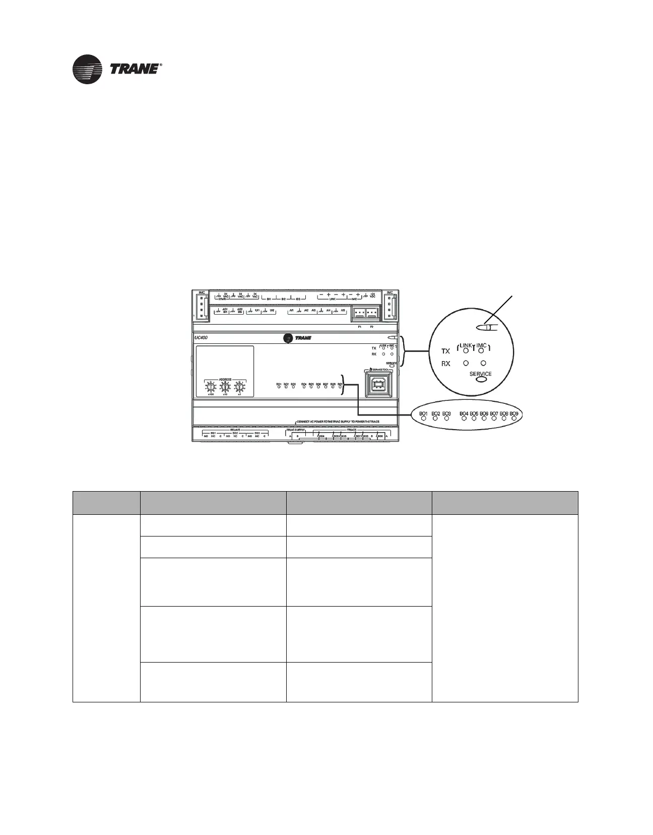
This section describes how to verify and interpret the UC400 controller LEDs and safely operate the
controller. LEDs are used to provide controller serviceability. The UC400 controller has the
following LEDs located on the front (refer to the illustration and Table 8 below):
• Marquee LED
• Communication status LEDs and IMC status LEDs
• Service button LED
• Three (3) binary output relay and six (6) TRIAC status LEDs
• For details about wiring communication links, refer
to the Tracer SC Unit Controller Wiring
Guide (BAS-SVN03).
Figure 5. Marquee LEDs
Table 8. LED Activities and Troubleshooting Tips
LED Name Activities
Indication and Troubleshooting
Tips Notes
Marquee LED
Shows solid green when the unit is
powered and no alarm
exists.
Indicates normal operation.
When powering the UC400 and
expansion mo
dule, the Marquee LED will
blink RED, blink GREEN (indicating
activated and controller/expansion
module are communicating), and then
stay GREEN CONTINUOSLY (indicating
normal power operation).
Shows blinking green during a device
res
et or
firmware download.
Indicates normal operation.
Shows solid red when the unit is
powered,
but represents low power or a
malfunction.
If low power; could be under voltage or
the
micro
processor has malfunction.
If malfunction; un-power and then re-
power unit to bring the unit back
up to
normal operation.
Shows blinking red when an alarm or
fault exist
s.
An alarm or fault condition will occur if
the value for a gi
ven point is invalid or
outside the configured limits for the
point. Alarm and fault conditions vary,
and they can be configured by the
programmer.
LED not lit.
Indicates power is OFF or there is a
mal
function
.
OFF or malfunction; cycle the power.

 Loading...


