VAV-SVX07F-EN 29
UC400 Controller Points and Parameters
• Airflow Setpoint (Active): Displays the active airflow setpoint. The airflow setpoint will be
determined based on the heat cool mode status, and the required heating or cooling capacity.
• Space CO
2
Concentration: CO
2
-based demand control ventilation uses the space CO
2
value.
The controller compares the space CO
2
concentration to the configured band of CO
2
values and
determines the demand ventilation rate of the zone. The resulting ventilation rate is called the
effective ventilation setpoint. The effective ventilation setpoint is the outdoor airflow required
to provide ventilation. It is used to calculate the ventilation ratio of the zone.
Space
• Space Temperature: The temperature, as reported by the zone sensor.
• Space Temperature (Active) Setpoint: The active (or
actual) setpoint currently used by the
Tracer UC400 controller. Can be either Heating or Cooling depending on operating mode.
• Space Temperature Setpoint BAS: Shows the
setpoint being communicated to the VAV unit
from a BAS system.
• Spac
e Temperature Setpoint Local: Displays setp
oint from local zone sensor.
• Space Temperature Setpoint Default: Disp
lays default configured setpoint.
• Discharge Air Temperature: Shows the discharge air temperatu
re input, which is the
temperature of the air leaving the VAV box.
• DA Temperature Setpoint BAS: Displays communicated
discharge air temperature setpoint,
if valid, when discharge air temperature control reset is enabled.
Ventilation.
• Ventilation Ratio: Required ratio of OA to primary air to meet zone ventilation need.
• Ventilation Setpoint: Arbitrated final value of the z
one ventilation requirement.
• Air Flow Stpt Active
Min: Displays active minimum flow setpoint.
Note: The UC400
may not be using the minimum flow setpoint if space conditions require
more airflow).
• Air Flow Stpt Active
Min Source: Displays the current minimum flow setpoint source.
Outputs
• Supply Fan Status: Indicates current fan On/Off status, or None if no fan present.
• Air Valve Position Command: Indicates desired air valve position.
• Heat Output Secondary Status: In
dicates Reheat Capacity Status in percentage.
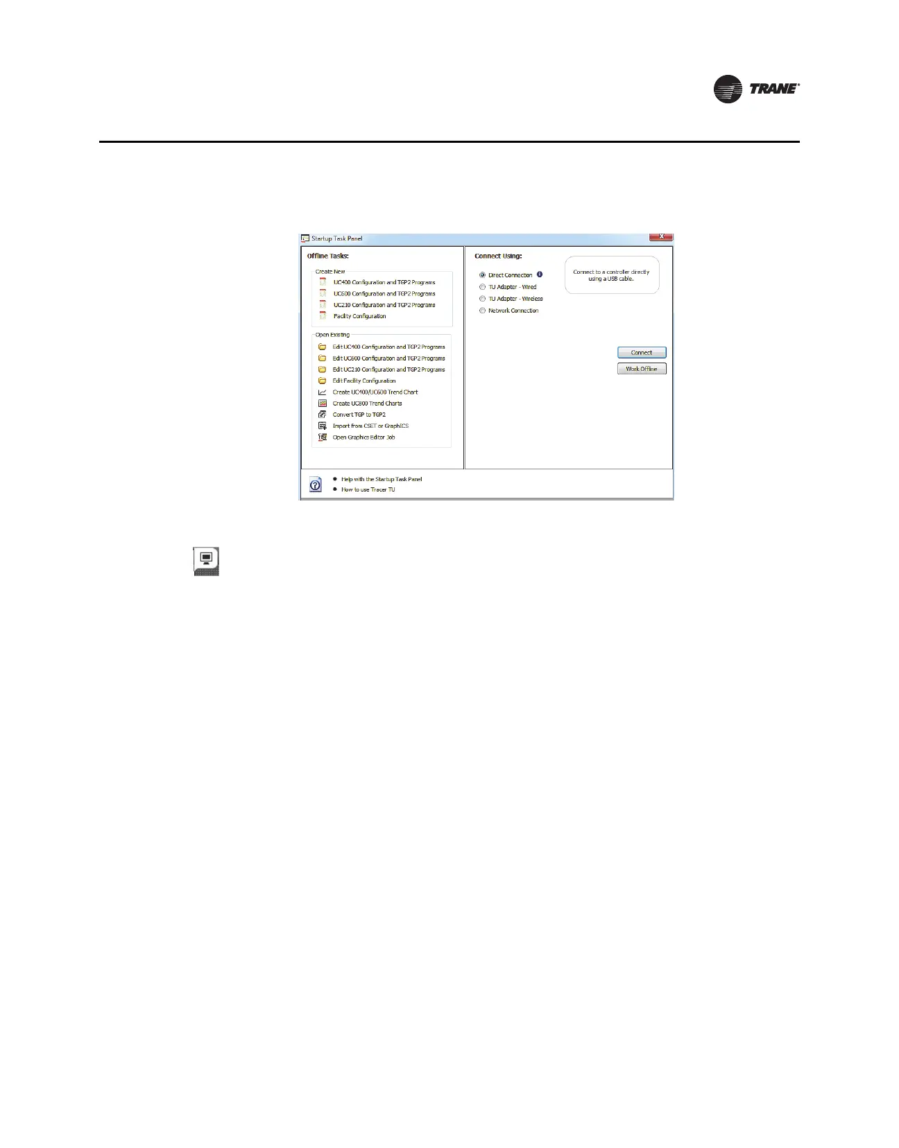
Analog, Binary, and Multi-state Screens
Use the Analog, Binary, and Multi-state screens to view input, output, and value points. These three
categories are presented in expanding boxes that stretch across the middle of each screen and are
defined from the factory.
Note: For field use of spa
re analog points, refer to the Tracer UC400 Programmable Controller
Installation, Operation, and Maintenance Manual (BAS-SVX20).

 Loading...


