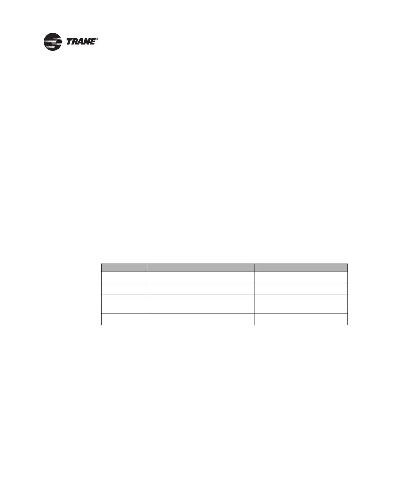
Table 11. Ventilation Flow Control Outputs
Occupancy
Mode Source Temperature Air Valve Control Reheat Control
Occupied, Occupied
Standby, or Occupied
Bypass
Any
Constant volume (if valid,
communicated
v
entilation setpoint; if not
valid, configured
ventilation setpoint)
Electric
VFC staged reheat
con
trol
Staged
hot water
VFC staged reheat
control
Modulatin
g hot water
VFC modulating reheat
con
trol (same as
STC
capacity control)
Unoccupied
Communicated source temperature (if valid; if
not vali
d, discharge air temperature) greater
than configured OA low limit.
Closed, 0%
Electric Off
Staged hot water Off
Modulating hot water Off
Communicated source temperature (if valid; if
not valid, di
scharge air temperature) less than
configured OA low limit.
Closed, 0%
Electric Off
Staged hot water
On, 100% freeze
protection
Modulating hot water
On, 100% freeze
protection
46 VAV-SVX07F-EN
Calibration, Operation Modes, and Control
The ventilation flow control process is a constant volume, variable temperature process. Single
duct VAV units with either electric or hot water reheat are used. Fan-powered units are not used
for ventilation flow control. Ventilation flow control must have a temperature sensor that is located
and setup as a discharge air temperature sensor. The required range of discharge air temperature
setpoints is from 19°F to 70°F (-7.22°C to 21.11°C).
Ventilation flow control staged reheat control (electric or hot water) achieves a 30-minute average
discharge air temperature to within ±5°F (±2.78°C) of the discharge air temperature setpoint when
the inlet temperature is within the control range. Ventilation flow control modulating reheat control
(hot water only) achieves a discharge air temperature to within ±5°F (±2.78°C) of the discharge air
temperature setpoint when the inlet temperature is within the control range.
Air Valve Control
Ventilation flow control uses the air valve as a constant volume device. The unit is given a constant
flow setpoint for air valve control (configured ventilation setpoint). The air valve only repositions
itself in response to changes in inlet static pressure. By using pressure-independent control for
ventilation purposes, a constant volume of fresh air can be maintained, regardless of small
fluctuations in inlet static pressure. Ventilation flow control unit can use a Ventilation Setpoint from
a BAS system, if it is valid. If the unit is standalone, the ventilation flow control uses one of the
following two (2) airflow setpoints:
• If no reheat being used, it uses the configured Ventilation Setpoint Local.
• If reheat being used, it uses the config
ured
Airflow Setpoint Minimum Local Heat.
Staged Reheat Control (Electric and Hot Water)
The heat outputs of the controller are binary. Only discrete levels of discharge air temperature are
possible. Since discrete discharge air temperature levels do not always provide an instantaneous
temperature within the required band, staged reheat controls to a 30-minute average discharge air
temperature. The discharge air temperature setpoint is limited from 19°F to 70°F (-7.22°C to 21.11°C).
Staged Electric Reheat Control
Units that are equipped with electric reheat should be sized so that the maximum temperature rise
across the heating elements is from 40°F to 48°F (4.44°C to 8.88°C); it should never exceed 50°F
(10°C) for safety reasons. These values were selected to allow the largest control range without
damage to the heater elements.

 Loading...


