Wiring requirements and options
CNT-SVX12C-EN 11
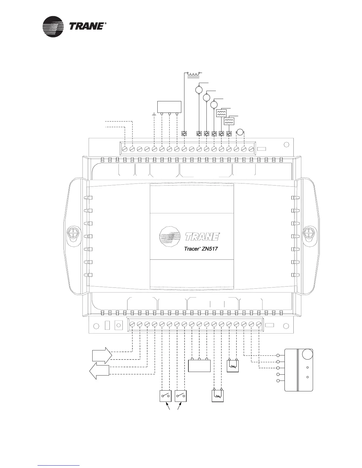
Figure 4. Wiring diagram for 2-heat/2-cool applications
LED
A BBA
+20GND
-BI2- SET-BI1- ZN
LED
GND
PIN
ZONE SENSOR
SERVICE
ANALOG INPUTS
COMM5
COMM5
24V
GND
HVAC UNIT
RhRc 1G 432 5NO 5COM
LED
STATUS5NC
BINARY INPUTS
AI1 -DAT-
24V
GND
GND
24V
OPN
CLS
BINARY OUTPUT
ECONOMIZERAC OUT
AC POWER
On
Cancel
5
4
3
2
1
+
_
GND
-AI2-
LonTalk
Occupancy
or generic
(optional)
Typical 3-wire
sensor
(optional)
Compressor 1 contactor
Heat stage 1
Tr i- st at e
modulating
economizer
(optional)
Fan
LonTalk
H
N
24 Vac
Generic binary output (optional)
Compressor 2 contactor
G
Y1
Y2
Heat stage 2
In
Out
(optional)
Fan status
(default:
normally closed
closed = no flow
open = flow)
or generic
Discharge air
temperature
Power*
R
W1 W2
Outdoor air
temperature
(optional)
*Terminals Rc and Rh are provided as
inputs for 24 Vac power from the con-
trolled device. If the device has a sepa-
rate heating and cooling units, use Rh
for heat and Rc for cooling. If com-
bined, use only Rc (see “HVAC unit
electrical circuit wiring” on page 82).
Dry contacts
only
Common

 Loading...


