AC power wiring
CNT-SVX12C-EN 85
AC power wiring
CAUTION
Equipment damage!
Complete input/output wiring before applying power to the Tracer
ZN517 unitary controller. Failure to do so may cause damage to the con-
troller or power transformer due to inadvertent connections to power
circuits.
CAUTION
Hazardous voltage!
Make sure that the 24 Vac transformer is properly grounded. Failure to
do so may result in damage to equipment and/or minor or moderate
injury.
IMPORTANT
Do not share 24 Vac between controllers.
All wiring must comply with National Electrical Code and local codes.
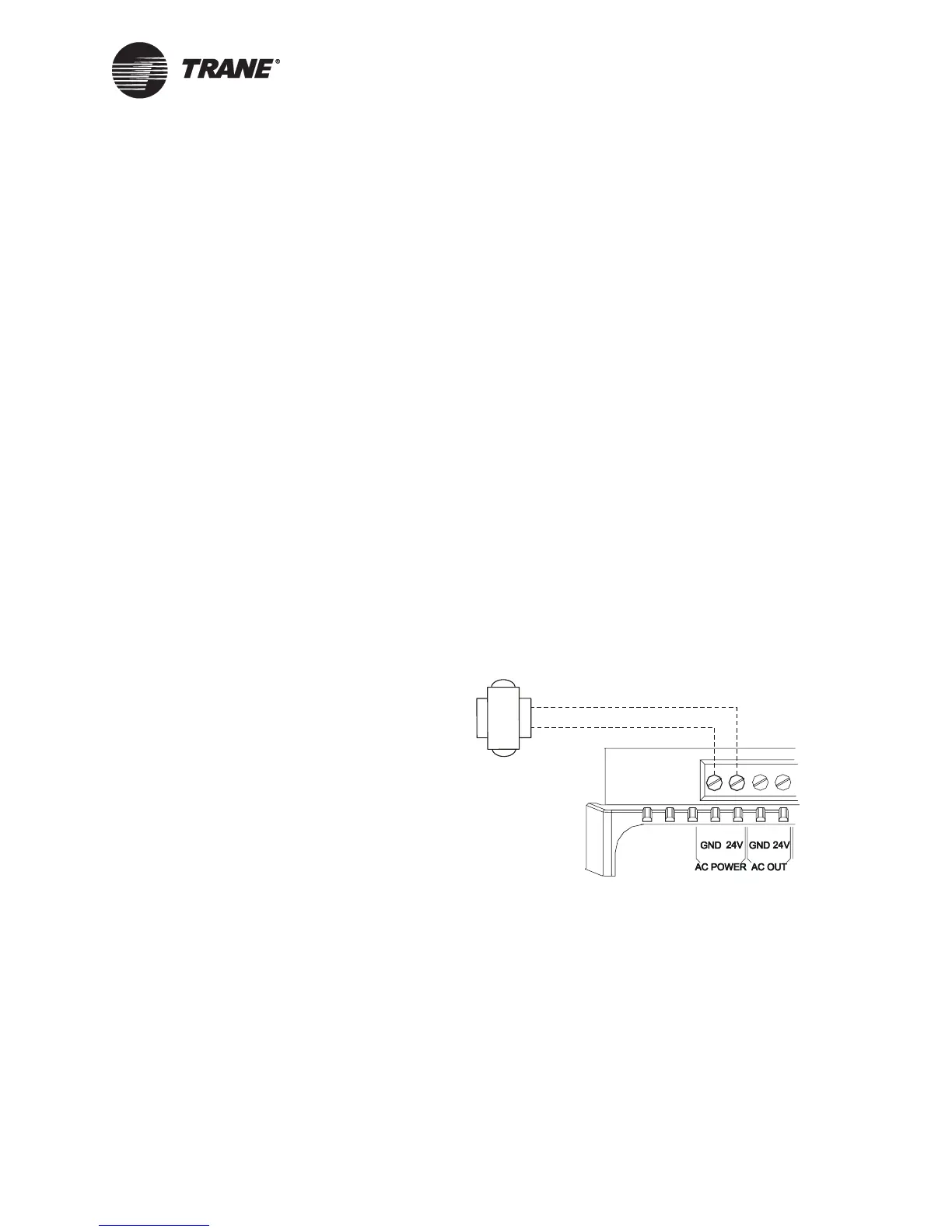
The ac power connections are in the top left corner of the Tracer ZN517
unitary controller (see Figure 32).
Figure 32. Connecting ac power wires to the controller
If you are providing a new transformer for power, use a UL-listed Class 2
power transformer supplying a nominal 24 Vac (19–30 Vac). The trans-
former must be sized to provide adequate power to the Tracer ZN517 uni-
tary controller (9 VA) and output devices, including relays and valve
actuators, to a maximum of 12 VA per output utilized. The Tracer ZN517
may be powered by an existing transformer integral to the controlled heat
pump, provided the transformer has adequate power available and ade-
quate grounding is observed.
24 Vac unit
transformer
H
N

 Loading...


