CNT-SVX12C-EN 73
Chapter 10
Status indicators for
operation and
communication
This chapter describes the operation and communication status indica-
tors on the Tracer ZN517 unitary controller, including:
• A description of the location and function of the Test button and Ser-
vice Pin button and the light-emitting diodes (LEDs)
• A complete list of the diagnostics that can occur, their effect on con-
troller outputs, and an explanation of how to clear diagnostics and
restore the device to normal operation
Test button
Use the Test button to perform the manual output test (see “Manual out-
put test” on page 74), which verifies that the controller is operating prop-
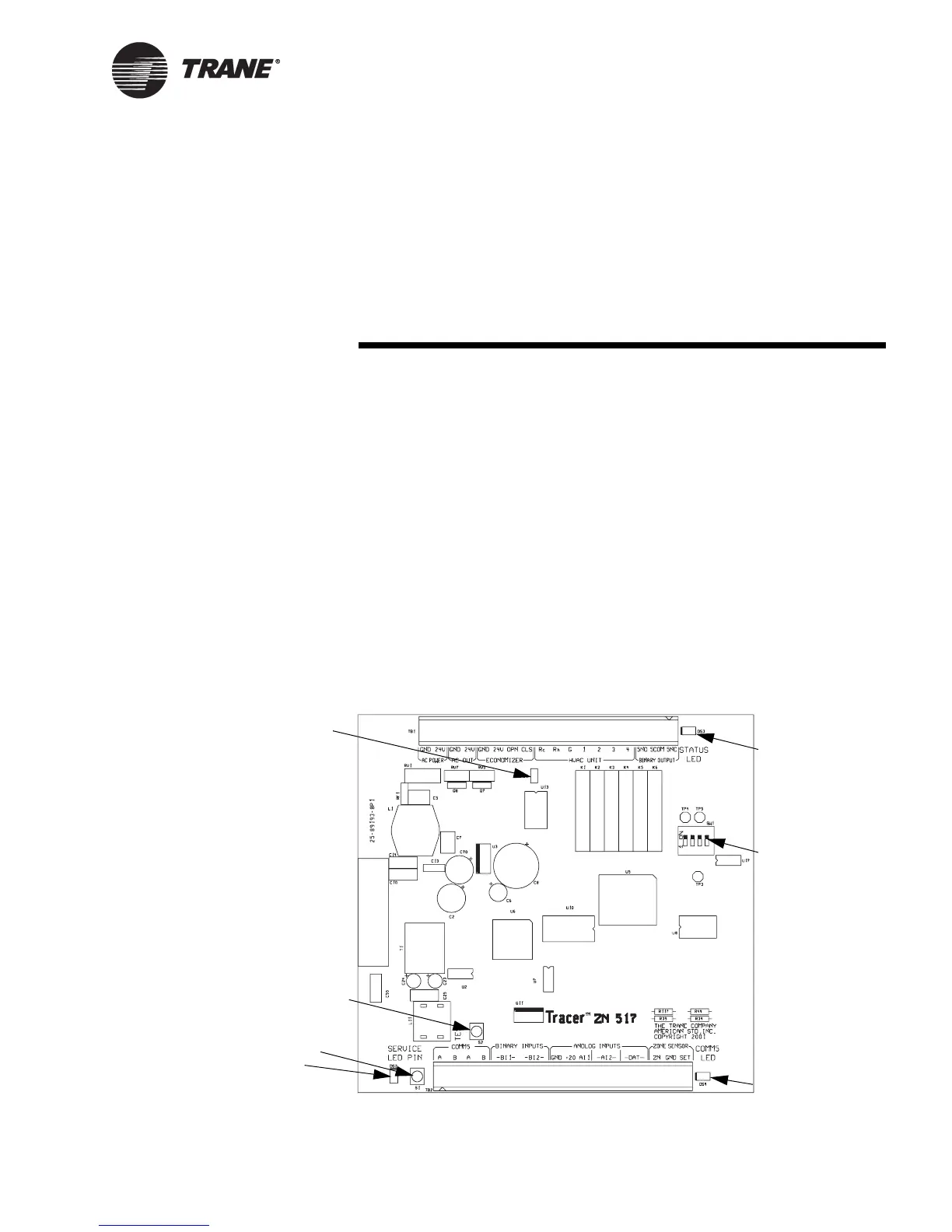
erly. Figure 27 shows its location.
Figure 27. Tracer ZN517 unitary controller circuit board
J1 (location of
jumper for Rc, Rh
terminals)
LonTalk LED (yellow)
Status LED (green)
Test b u tt o n
Service Pin button
DIP switches
Service LED (red)

 Loading...


