CNT-SVX12C-EN 63
Chapter 9
PID control
This chapter will help you set up, tune, and troubleshoot proportional,
integral, derivative (PID) control loops used in the Tracer ZN517 unitary
controller. For more information about PID loops, see BAS-APG002, PID
Control in Tracer Multi-Purpose Controllers.
PID control requires the use of a Rover service tool. All PID factory
defaults can be restored by clicking the Use Defaults button.
What PID loops do
A PID loop automatically controls an output to maintain a measured
value at its setpoint by monitoring the error (the difference between the
measured value and the setpoint). The loop performs proportional, inte-
gral, and derivative calculations to determine how aggressively to change
the output.
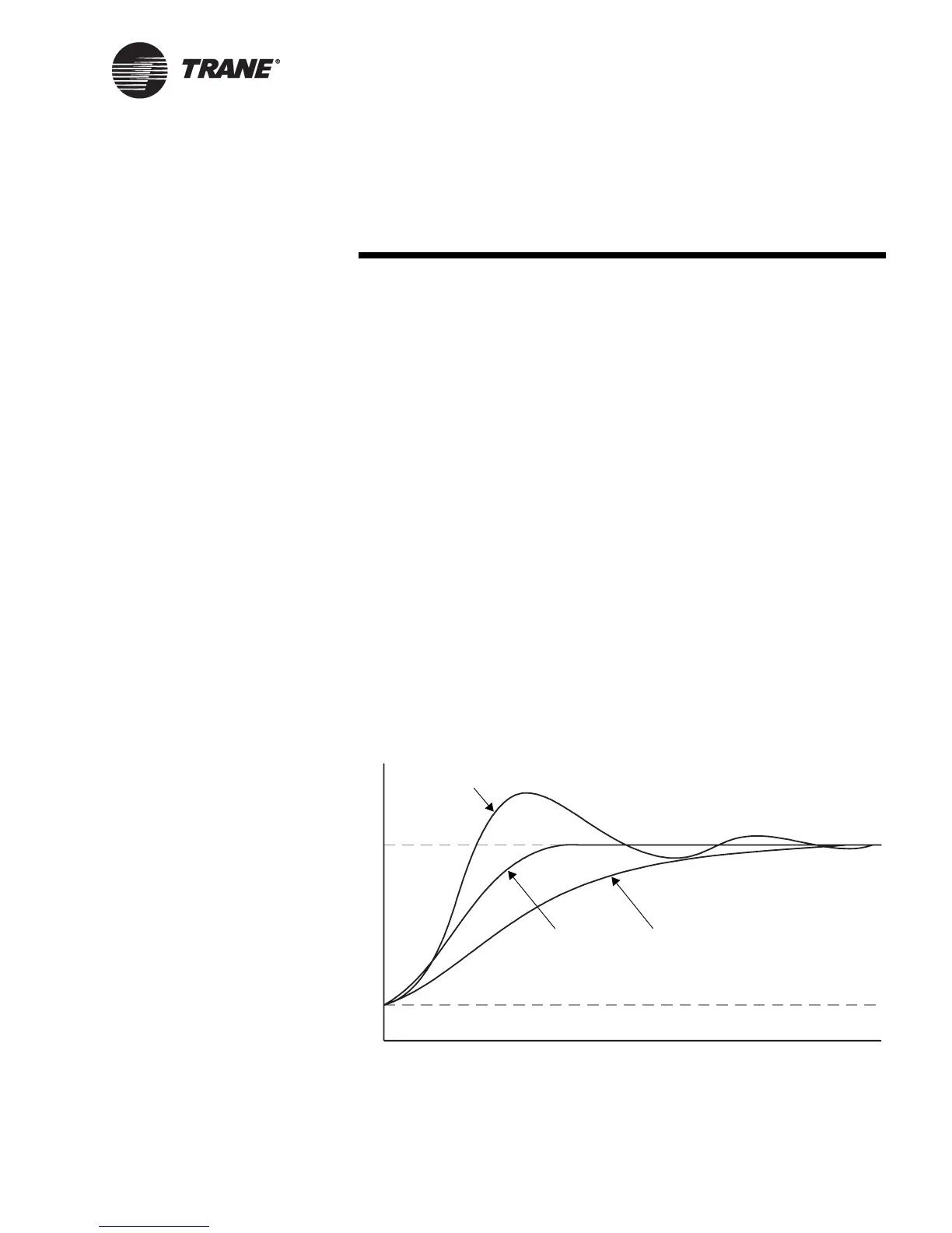
The goal of PID control is to reach the setpoint as quickly as possible
without overshooting the setpoint or destabilizing the system and to
maintain the setpoint consistently over time. If the system is too aggres-
sive, it will overshoot the setpoint as shown in Figure 19. If it is not
aggressive enough, the time to reach the setpoint will be unacceptably
slow.
Figure 19. The effects of PID aggressiveness
Setpoint
Initial point
Too aggressive (overshoot)
Too slow
Time
Ideal response
Measured value

 Loading...


