Chapter 3 Applications for the 2-heat/2-cool configuration
16 CNT-SVX12C-EN
tion.) The sensor communicates a value of 0–100% to the BAS. This con-
figuration has no direct effect on Tracer ZN517 operation.
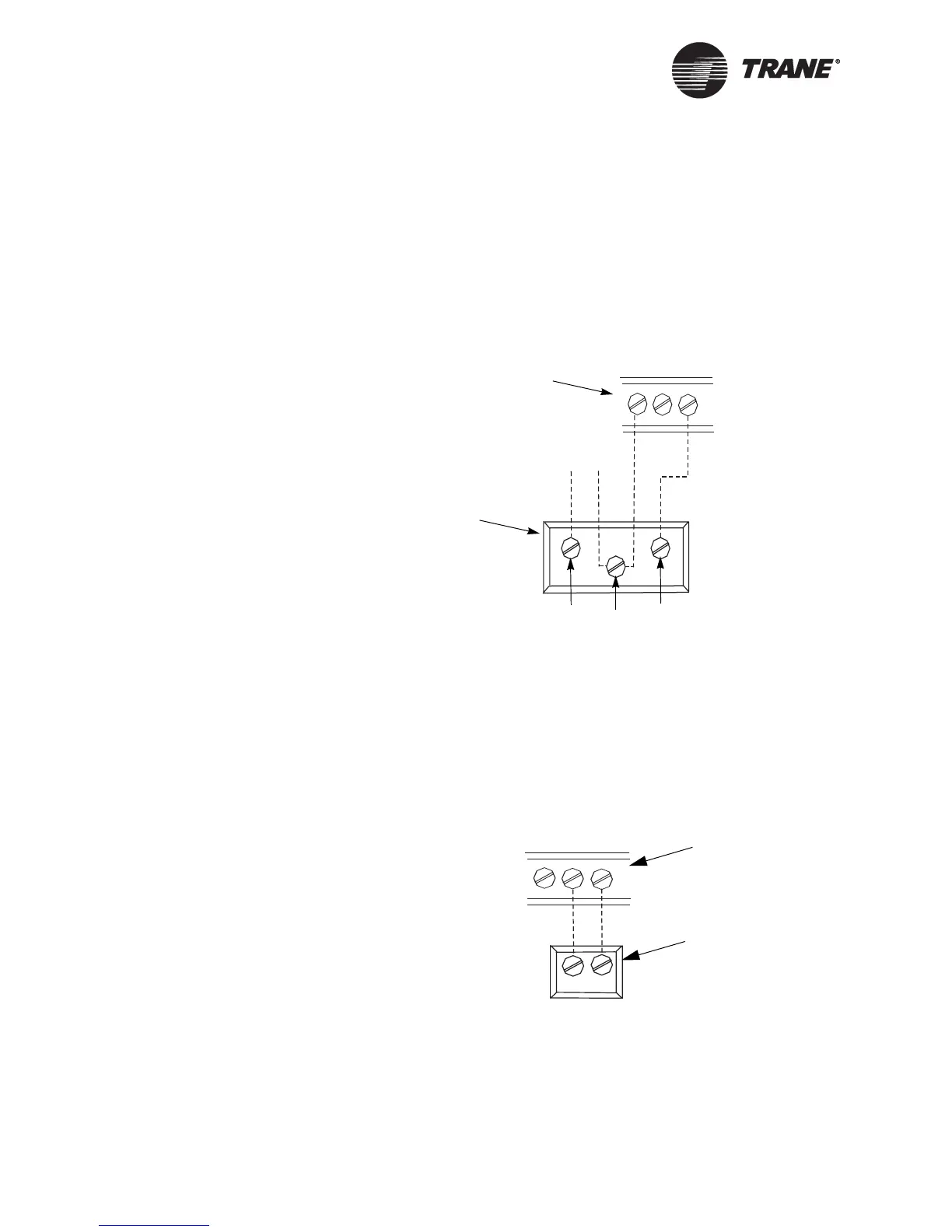
For the CO
2
measurement configuration, a 4–20 mA sensor must be hard-
wired to the AI1 terminal as shown in Figure 6. The sensor will transmit
a 0–2000 ppm value to the BAS. This configuration has no direct effect on
Tracer ZN517 operation. If a valid value is established and then is no
longer present, the controller generates a CO
2
Sensor Failure diagnostic.
Figure 6. AI1 terminal wiring: CO
2
measurement
For the RH measurement configuration, a hard-wired 4–20 mA zone
humidity sensor (see Figure 7) must provide a value to the controller. If a
valid hard-wired or communicated relative humidity value is established
and then is no longer present, the controller generates an RH Sensor Fail-
ure diagnostic and disables the dehumidification function. The RH sensor
is used only to provide a valid humidity reading to a BAS; it does not
affect the operation of the Tracer ZN517.
Figure 7. AI1 terminal wiring: RH measurement
{{
+20GND
AI1
Tracer ZN517
24 Vac
CO
2
sensor
(Trane part number:
4190 4100 or 4190 4101)
GND
Out
24 Vac
+
–
+20GND
AI1
Tracer ZN517
RH sensor
Figure Note:
The +20 terminal provides 20 ±2 Vdc that is used to power a Trane RH sensor (part
numbers 4190 1109, 4190 7011, 4190 7012, 4190 7014).

 Loading...


