114 UNT-SVX07B-EN
Diagnostics
Switch SW1: Controller Type
SW1 determines the unit control type.
Position 1 indicates one of the following:
• generic field controller
• low-voltage fan speed switch
• Tracer ZN010
• Tracer ZN510
Position 2 indicates Tracer ZN520.
Switch SW2: Electric Heat
SW2 determines if the unit has electric heat.
Switch SW3: High-Speed Interlock
SW3 determines if the unit will have a safety-mandated “high-speed interlock” with electric heat.
High-speed interlock ensures heat dissipates in a manner that keeps the unit in a safe operating
condition. SW3 configures the unit to actuate high-speed interlock if the first or second stage is on.
SW3 is a three-position slide switch that actuates high-speed interlock to operate with specific
electric heat coils.
• Position 1: default position and for lo
w vertical units with electric heat
• Position 2: single-stage electric heat, model number digit 18 = N
• Position 3: two-stage electric
Switch SW4: Electric Heat Lockout
SW4 allows the unit to use the electric heat lockout function when hydronic heat is in operation.
Electric heat lockout prevents electric heat from enabling when hydronic heating is available. This
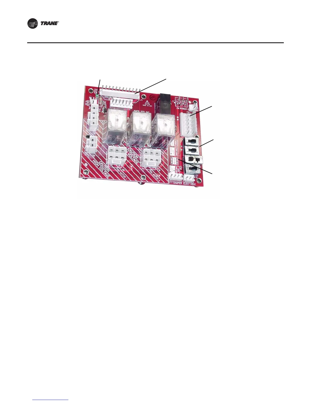
Figure 29. Relay board detail
LED Indicates Power
Interface to Tracer ZN Controller
Configuration Switches
(Factor Pre-set)
Do Not Adjust These
Switch Positions
Because it May Result
in a Safety Hazard!
Connection to Valve and
Piping Sensor Crossover
Harness
Note: HAZARDOUS Voltage in
Dashed Area of Board!

 Loading...


