UNT-SVX07B-EN 11 3
Diagnostics
Troubleshooting
Troubleshooting the Relay (Daughter) Board
The relay board serves as a common interface to all of the standard end devices, and has an LED
that indicates power to the board. Factory switches are pre-set and locked in place with LocTite
®
.
However, these seals can be broken if field-modifications are needed.
If the board needs replacement, the switches on the new board must be field-set in the same
positions as the old board, as shown in the unit wiring diagram.
Note: SW3 and SW4 affect safety functionality, and they are factory secured. When replacing a
board with SW3 and SW4, be sure to affix the switch positions with 3M 3764Q or equivalent.
Board switches are factory set based on unit control options. Figure 29 shows a relay board detail.
Additional information on switch settings follows.
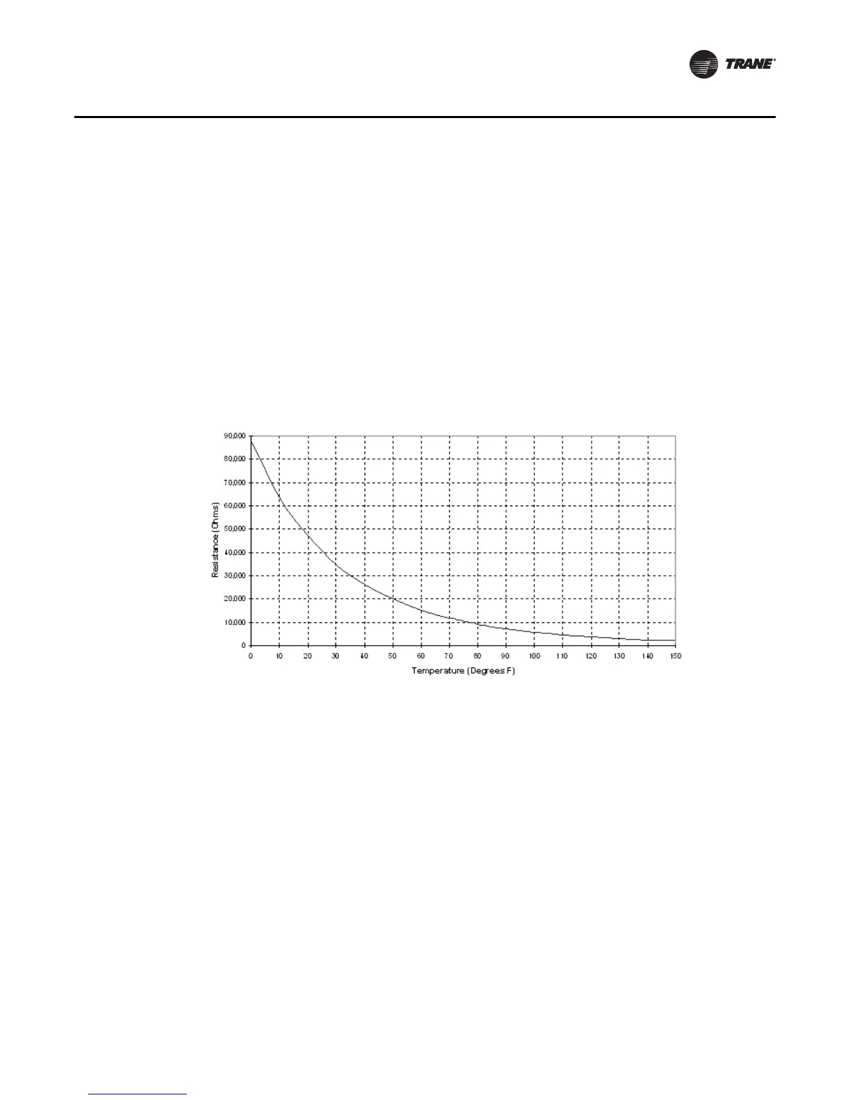
Figure 28. Resistance temperature curve for the zone sensor, entering water temperature sensor,
and discharge air sensor (thermistor = 10kΩ at 77°F)

 Loading...


