UNT-SVX07B-EN 57
Installation—Controls
Location Considerations
Placement of the sensor is critical to proper operation (the receiver is factory mounted on fan-coil
units). For most installations, barriers limit proper radio signal strength more than distance. For
best radio transmission range and reliability, mount the receiver and sensor in line of sight. Where
this is not possible, try to minimize the number of barriers between the pair of devices. In general,
sheetrock walls and ceiling tiles offer little restriction to the transmission of the radio signal
throughout the building.
The transmission range for the sensor is as follows:
• Open range: 2,500 ft (762 m) (packet error rate = 2%)
• Usable range: 200 ft (61 m)
• Typical range: 75 ft (23 m)
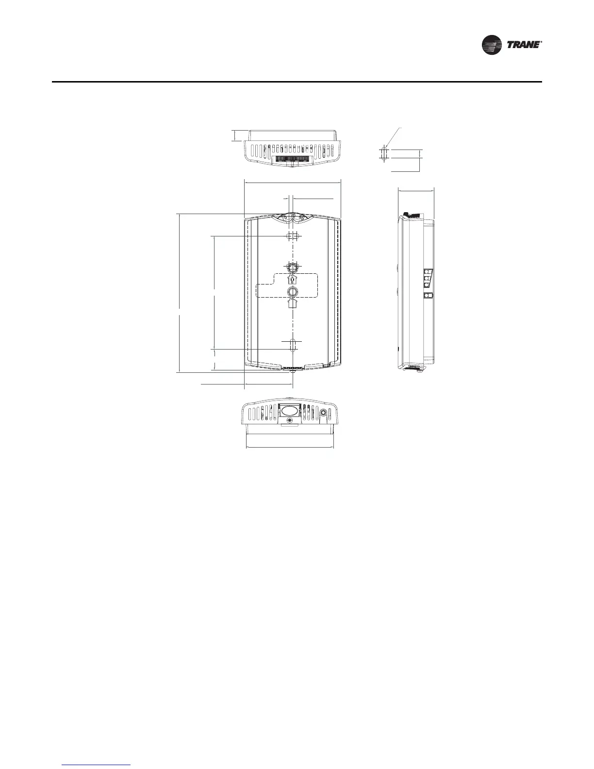
Mounting the Sensor Back Plate
To mount the sensor back plate:
1. Hold the back plate against the mounting surface and mark the screw locations.
2. Secure the back plate against the mounting surface using included hardware.
The following figure shows an example of mounting the back plate of the sensor into sheetrock
or plaster.
0.31 in (8 mm)
TYP R.07 in
(R1.9 mm)
2.9 in (73.5 mm)
TYP 0.24 in (6 mm)
1.08 in (27.5 mm)
0.12 in (3 mm)
3.39 in (86 mm)
4.68 in (118.9 mm)
0.63 in (15.9 mm)
1.45 in (36.8 mm)
2.62 in (66.5 mm)