UNT-SVX07B-EN 39
Installation—Mechanical
Install a secondary overflow drain line if necessary by punching out the overflow drain nipple on
the auxiliary drain pan. Next, place a
3
/
8
-inch inside diameter flexible plastic tube over the nipple
and secure with a field supplied hose clamp.
Note: The installer is responsible for adequately insulating field piping. See the “External
Insulating Requirements section for more information.
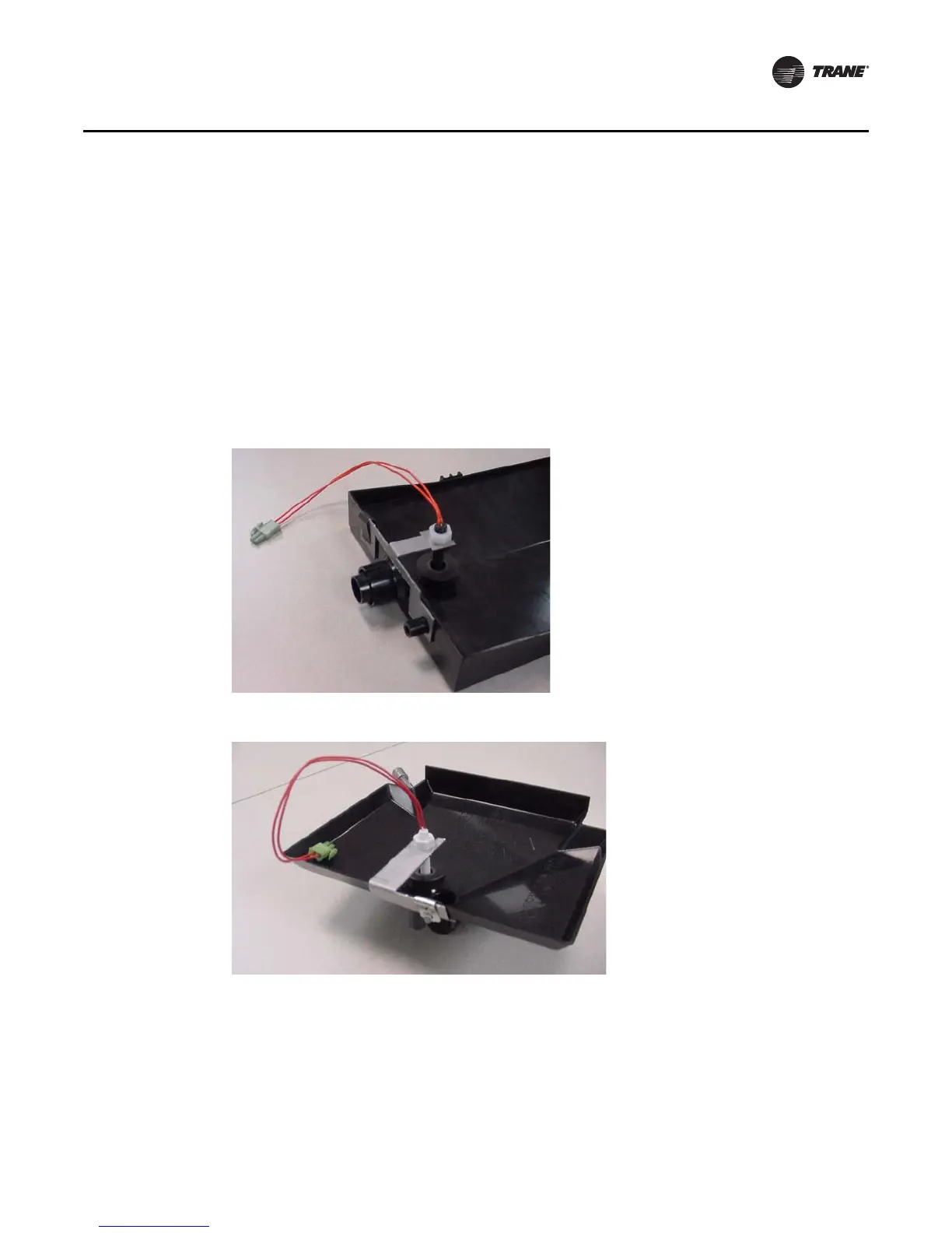
Condensate Overflow Detection Device
The condensate overflow detection device is an option on fan-coil units with either a Tracer ZN010,
ZN510, ZN520, or the customer-supplied control interface. The float switch, mounting bracket, and
coiled leads ship attached inside the piping end pocket of the unit. Install the switch by placing the
hole or slot in the bracket over the condensate overflow drain (of the auxiliary drain pan) with the
switch float extending over the pan. Secure the drain pan by attaching the pan’s bracket with the
factory provided clip. See Figure 3 and Figure 4.
Automatic Changeover Sensor
Two-pipe changeover units with either the Tracer ZN010, ZN510, and ZN520 controls have an
automatic changeover sensor that determines heating or cooling mode based on the supply water
temperature. On units with a factory piping package, the factory straps the changeover sensor to
the piping supply water pipe. See Figure 5, p. 40 and Figure 6, p. 40.
Figure 3. Condensate float switch installed in horizontal auxiliary drain pan
Figure 4. Condensate float switch installed in vertical auxiliary drain pan