UNT-SVX07B-EN 41
Installation—Mechanical
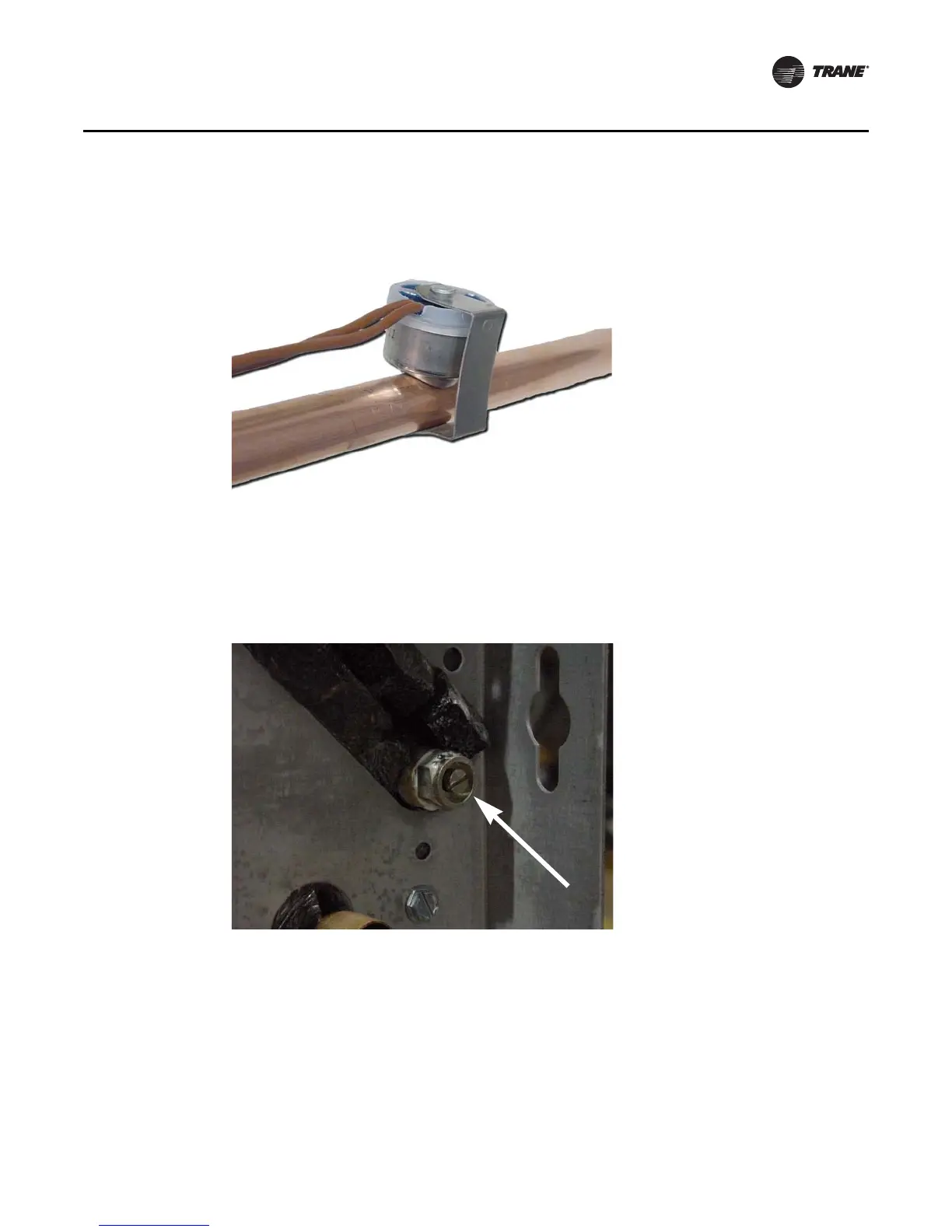
If the fan-coil unit does not have a factory piping package, the switch and coiled lead wires ship
inside the piping side end panel. The installer should position the lockout switch on the supply
water line of the unit by sliding its spring connector over the pipe. See Figure 7.
Venting the Hydronic Coil
The hydronic coil contains a vent, either manual or automatic, to release air from the unit. This vent
is not sufficient for venting the water piping system in the building.
The coil air vent is on the piping side, above the coil connections on the unit. See Figure 8 and
Figure 9. Perform the following steps to vent the coil after installing the unit.
Figure 7. Electric heat lock out switch installed
Figure 8. Manual coil air vent with set screw