RT-SVX34C-EN 23
Unit Dimensions and Weights
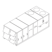
Figure 12. Unit Rigging
Table 1. Minimum Operating Clearances Installation (Horizontal and Downflow Configurations)
Recommended Clearances
Single Unit
Economizer/
Exhaust End
Condenser Coil
(a)
Orientation End/Side
(a) Condenser coil is located at the end and side of the unit.
Service Side Access
TC*, TE*, YC*
27.5 to 50 Tons
6 Feet 8 Feet 4 Feet
Distance Between Units
Multiple Unit
Economizer/
Exhaust End End/Side Service Side Access
TC*, TE*, YC*
27.5 to 50 Tons
12 Feet 16 Feet 8 Feet
Table 2. Maximum Slope
Cabinet End to End (inches) Side to Side (inches)
"A" (27.5 - 35 Ton Low Heat) 3 1/2 1 5/8
"B" (27.5 - 35 Ton High Heat) 4 1 5/8
"C" (All 40 and 50 Ton Units) 4 1/2 1 5/8
Note: Do not exceed these allowances. Correct the improper slope by building up the curb base. The material used to raise
the base must be adequate to support both the curb and the unit weight.

 Loading...


