12
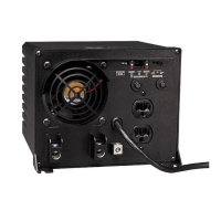
AC Input/Output Connection
AC Generator Input
To avoid overloading your Inverter/Charger, be sure to match the power requirements of the equipment you plan to run at any one time
(add their total watts) with the output wattage capacity of your Inverter/Charger model. When figuring the power requirements of your
equipment, do not confuse “continuous” wattage with “peak” wattage ratings. Most electric motors require extra power at start-up
(“peak” wattage) than required to run continuously after start-up, sometimes over 100% more. Some motors, such as in refrigerators and
pumps, start and stop intermittently according to demand, requiring “peak” wattage at multiple, unpredictable times during operation.
DoubleBoost™ Feature
Tripp Lite Inverter/Chargers deliver up to twice their nameplate rated wattage for up to 10 seconds,* providing the extra power needed to
cold start heavy-duty tools and equipment.
OverPower™ Feature
Tripp Lite Inverter/Chargers deliver up to 150% of their nameplate-rated wattage for up to 60 seconds under ideal battery and
temperature conditions*, providing reserve power to support tools and equipment.
* For best results, utilize for as short a duration as possible, ensure that battery bank and cabling are able to provide full nominal DC voltage under load, and allow the inverter/
charger to cool completely before and after utilization.
WARNING! Consult a qualified electrician and follow all applicable electrical codes and
requirements for hardwire connection. Disconnect both DC input and AC utility supply before
attempting hardwiring. Over-current protection is to be provided in accordance with local
and/or national electrical codes. Refer to nameplate on unit for input and output current
ratings. Use a 30A input and 15A output overcurrent protector. Use wire with a minimum
temperature rating of 90º C. A readily visible and adequate disconnect device must be provided.
The inverter/charger is designed to provide heavy-duty power to both the AC output load and the DC battery charging load at the same
time. The amount of additional input power required is determined by the setting of the AC Input Current Sharing DIP switches (switches
7 and 8 - see the Configuration section for switch settings). The recommended minimum VA rating for AC generator input is shown in
the table below.
Minimum Recommended AC Generator VA Rating
AC Input Current Sharing APSX3024SW
Most Limiting 3750VA
Less Limiting 4900VA
Least Limiting 6000VA
No Limiting 7200VA
NOTE: If the applied AC load is significantly less than that of the
Inverter/Charger’s AC output rating, a smaller size generator may
be used by setting the battery charger DIP Switch to the low DC
current setting. The minimum recommended VA rating for the AC
generator would then be the VA needed for the Charger (1100
VA for APSX3024SW, plus the VA required for the load.
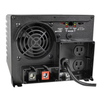
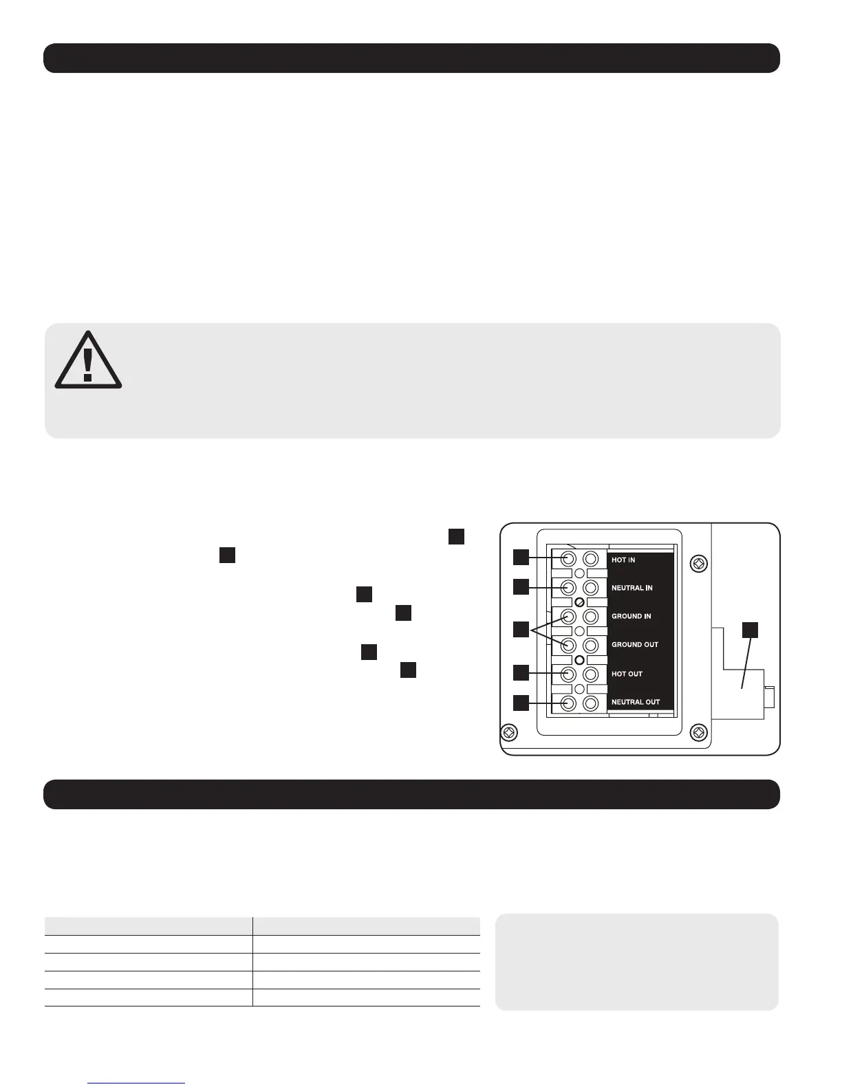
Remove the screws and cover plate over the hardwire terminal strip. Remove the knockout covers closest to the desired electrical source
and to your equipment. Attach 13 mm (0.5 inch) diameter conduits (user-supplied) to the knockouts and thread wires through. Connect
the conduits to each other with the ground bond connection supplied. Tighten all wire terminals to a minimum 2.3 N•m torque to create
an efficient connection and reduce resistive heating.
1
5
6
4
2
3
Ground*
• Connect the incoming and outgoing ground wires to the ground terminals
1
.
• Connect the Main Ground Lug
2
to earth ground.
AC Input (Use 90° C, 10 AWG copper wire)
• Connect the incoming hot wire to the input hot terminal
3
.
• Connect the incoming neutral wire to the input neutral terminal
4
.
AC Output (Use 90° C, 12 AWG copper wire)
• Connect the outgoing hot wire to the output hot terminal
5
.
• Connect the outgoing neutral wire to the output neutral terminal
6
.
Replace cover plate and tighten screws.
* If the incoming conduit only contains two wires (hot and neutral), the incoming conduit must be
bonded to the main ground lug on the unit. In any case, the incoming conduit must be bonded to earth
ground, and the incoming conduit must be bonded to the outgoing conduit.
 Loading...