16
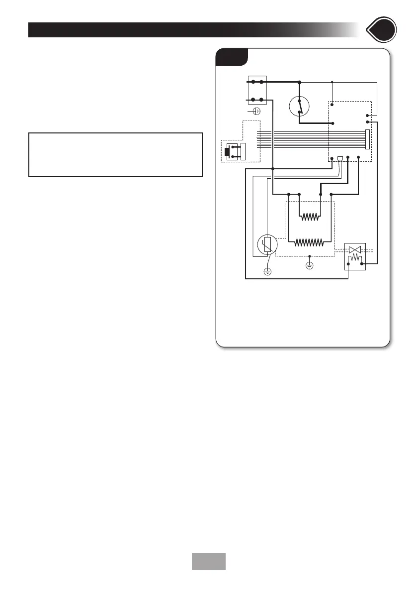
Fig.13 shows a schematic wiring diagram.
• The use of connections within the unit or
other points in the shower circuit to supply
power to other equipment i.e. extractor fans,
pumps etc., will invalidate the guarantee.
• DO NOT switch on the electricity supply
until the shower cover has been fitted.
7
SECTIONSECTION
NOTE: The elements on UK models are to
240V specification and will give a lower kW
rating if the voltage supply is below 240V.
Fig.13
L
N
E
1
2
3
5
7
6
inlet
outlet
9
9
4
8
1. Terminal block
2. Earth post
3. Control PCB
4. Power PCB
5. Solenoid Valve
6. Thermal cut-out
7. Thermistor
8. Connector socket
9. Element
Installation -
FIT TO THE WALL & CONNECT THE SHOWER SUPPLIES