T100e thermostatic care & care plus
11
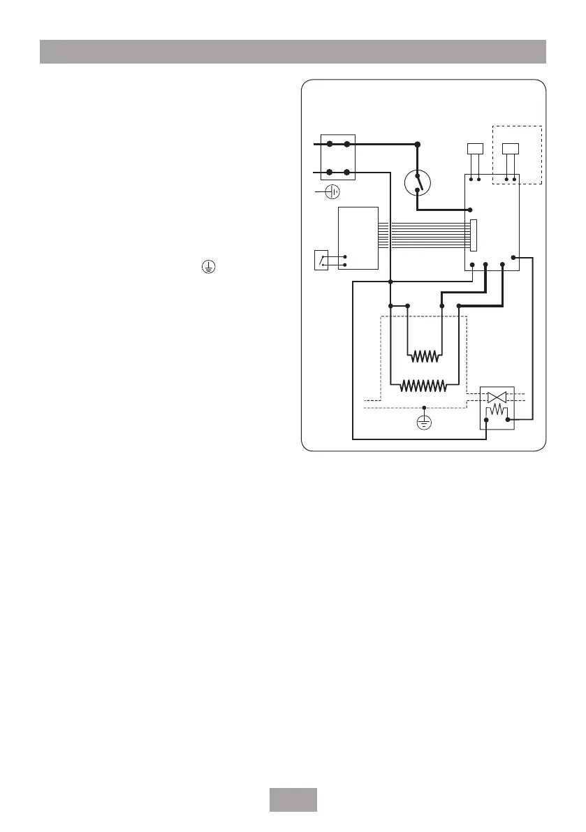
Fig.17 shows a schematic wiring diagram.
The cable entry points are top, bottom or back.
The cable can be surface clipped, hidden or via
20 mm conduit.
Note: Conduit entry can only be from rear.
SWITCH OFF THE ELECTRICITY SUPPLY AT
THE MAINS.
Route the cable into the shower unit and
connect to the terminal block as follows:
Earth cable to terminal marked
Neutral cable to terminal marked N
Live cable to terminal marked L
IMPORTANT: Fully tighten the terminal
block screws and make sure that no cable
insulation is trapped under the screws. Loose
connections can result in cable overheating.
Note: The supply cable earth conductor must
be sleeved. The outer sheath of the supply cable
must be stripped back to the minimum.
The supply cable must be secured either by
routing through conduit or in trunking or by
embedding in the wall, in accordance with
current IEE regulations.
The use of connections within the unit to supply
power to other equipment i.e. extractor fans,
pumps etc. will invalidate the guarantee.
DO NOT switch on the electricity supply until
the cover has been fitted.
Note: The elements on UK models are to 240V
specifications and will give a lower kW rating if
the voltage supply is below 240V.
L
N
E
Start/stop
switch
Control
PCB
Power
PCB
Connector
socket
Terminal
block
Thermal
cut-out
Pressure
switch
Thermistor
Earth
post
inlet
Solenoid
valve
outlet
Elements
Care Plus only
Fig.17
Electrical connections