T100e thermostatic care & care plus
8
W-005-A
WARNING!
Check there are no hidden cables or
pipes before drilling holes for wall
plugs. Use great care when using power
tools near water. The use of a residual
current device (RCD) is recommended.
Note: The control lever is an integral part of the
cover — DO NOT attempt to remove it.
Unscrew the two top and one bottom retaining
screws. There is no need to completely remove
the screws, just enough to lift the cover from the
backplate. To allow access for the pipe and cable
connections, remove the trimplate by lifting it
away from the backplate.
Entry positions for the mains water are from the
top, bottom or back. Cable entry is via the top,
bottom or back.
Note: Deviations from the designated entry
points will invalidate product approvals.
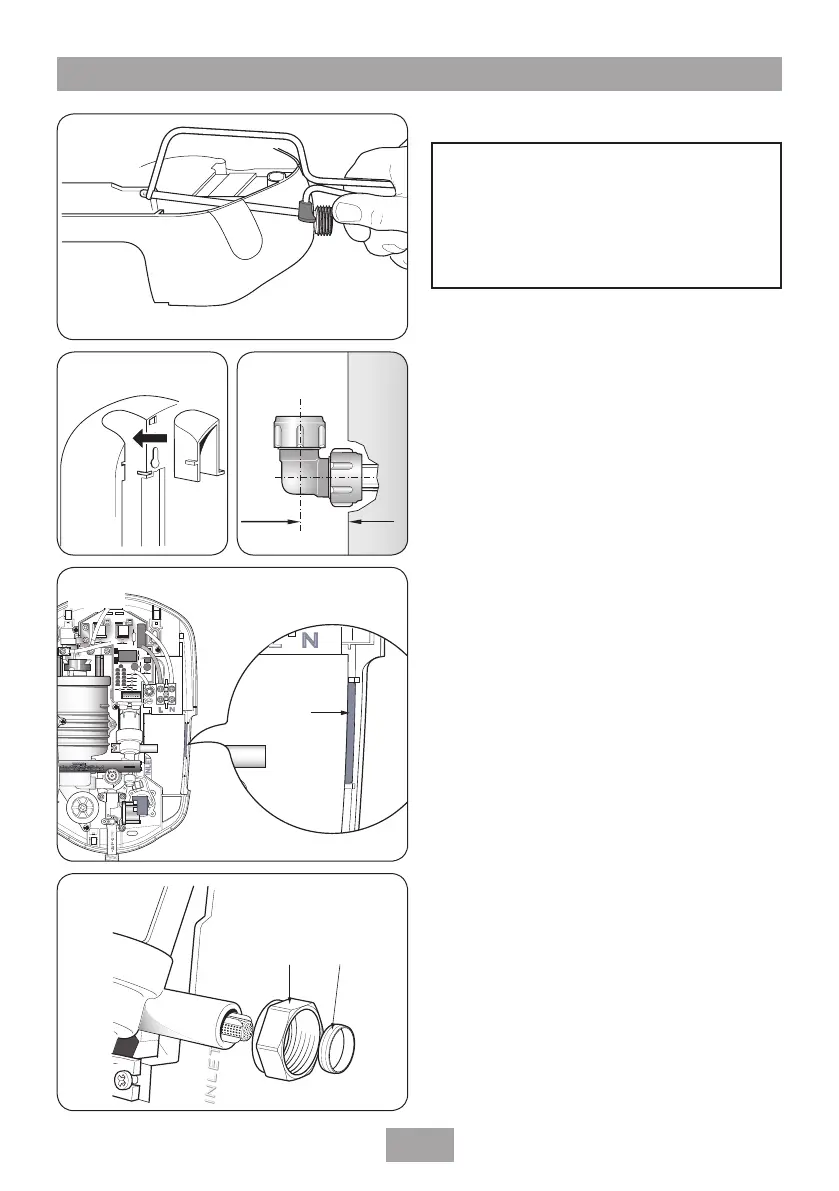
If bottom surface entry is required, then the
necessary hole will need to be cut out in the
thinned section of the trimplate using a junior
hacksaw and file (fig.8).
If bottom or rear entry is chosen, the pipe trim
will need to be fitted in the top entry position on
the backplate (fig.9). The pipe trim is packaged
separately.
If installing a supply pipe from the bottom, the
centre of the inlet valve to the wall surface is
21 mm.
If entry is from the back, the nut of the
compression fitting will be partially behind the
surface of the wall. This area MUST be left clear
when plastering over the pipework to make the
nut accessible for future adjustments.
Note: the distance between the centre of the
inlet valve and the wall is 21 mm (fig.10).
To ease the installation of the unit remove the
shaded area shown in fig.11.
Fig.8
Fig.9
Fig.10
INLET
L
L
N
N
INLET
N
N
Area to be
removed
Fig.11
Fig.12
Fitting the shower to the wall
FITTING THE SHOWER TO THE WALL