CHAPTER 2: ASSEMBLY GUIDE
Truetness.com / 800.426.6570 / 636.272.7100
30 of 171
TREADMILL ASSEMBLY STEPS:
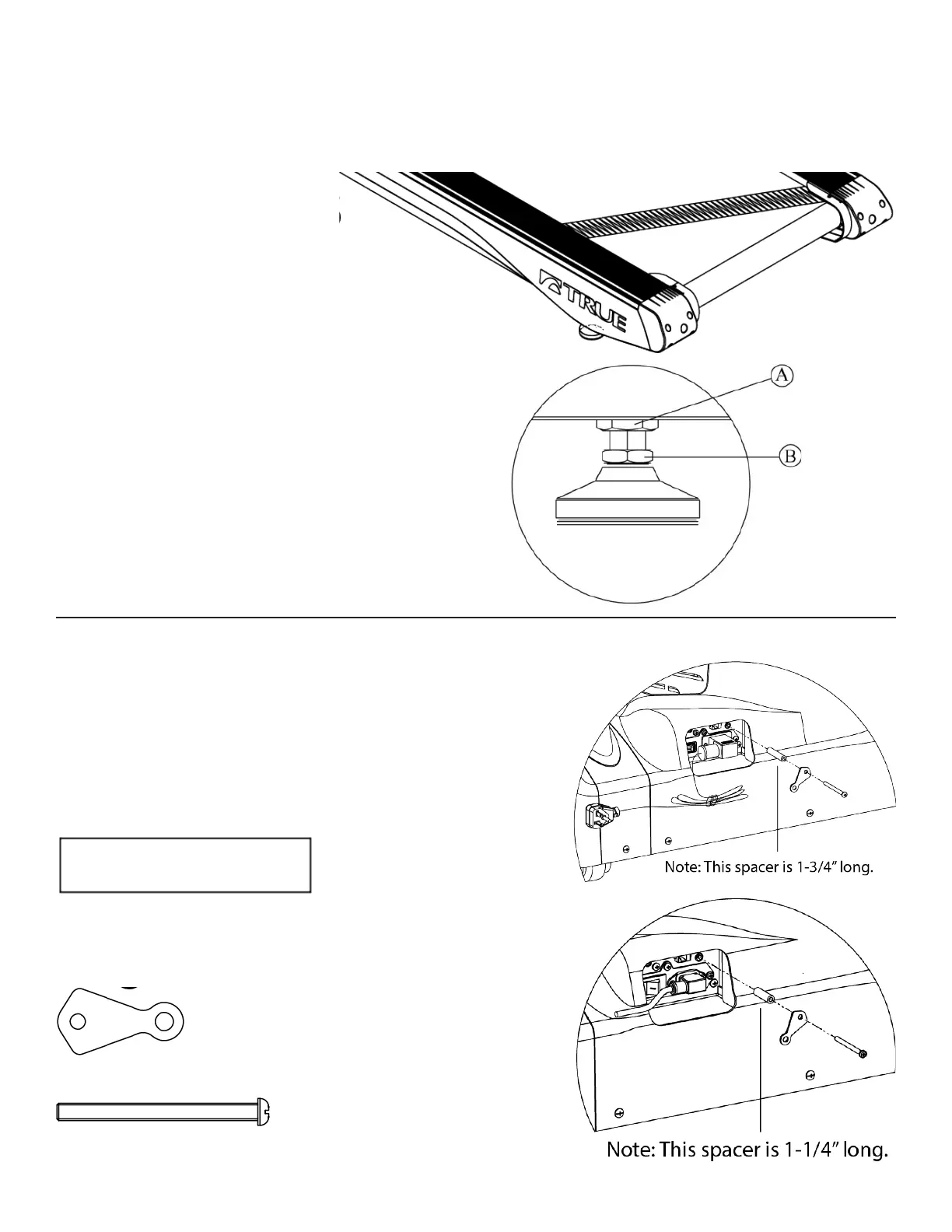
Step 17 Rear Foot Leveling:
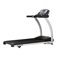
Step 18 Power Cord Retainer:
a) Ensure treadmill incline rack
wheels and rear feet are resting on
the oor and not on cardboard,
packaging, etc.
b) Using a 15/16 inch open
end wrench, loosen nut A on
Right Rear Foot (only side
adjustable).
c) Using a level or estimating by sight,
turn section B of foot clockwise, or
counter-clockwise, using a 7/8 inch
open end wrench to level the rear of
treadmill.
d) Tighten nut A until it is secured
against bottom of treadmill.
Note: e recommended gap between
(A) and (B) is 1/4” on a at oor.
a) Install the power cord retainer assembly in
the order shown, but do no tighten.
b) Rotate power cord retainer down and
tighten the screw to push the retainer up
against the power cord.
Hardware Required:
1 spacer
Note: e 110V spacer is 1-3/4” long.
e 220V spacer is 1-1/4” long.
1 retainer-power cord
1 bolt M5 x 60
110V
conguration
220V
conguration