23
Wiring of the safety socket with the
micro switch
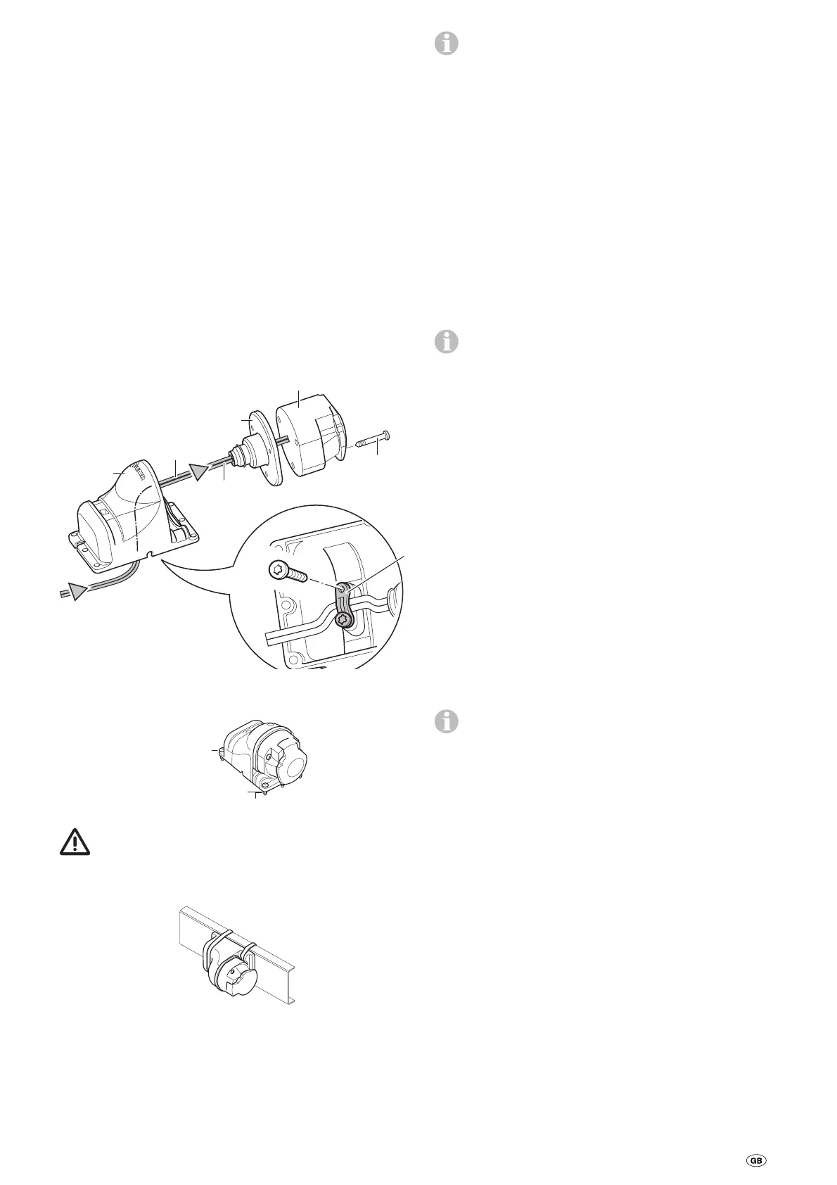
Guide the enclosed 2-wire cable with the flat connector
through the socket holder (g) and the rubber coupling (h).
If necessary, open the cover and press the socket connection
out of the socket housing (i).
Insert the 2-wire cable with the flat connector into the micro
switch.
If necessary, reinsert the socket connection into the socket
housing (i).
Screw socket housing (i) to socket holder (g) using 3 sheet
metal screws (j). (Several alternative positions are available by
using the mounting holes in the socket holder and rotating
the rubber seal.)
Loosely route cable through strain relief (k) and secure with
2 sheet metal screws. Depending on the installation situation,
the cable can be led out of the socket holder through one of
the three recesses.
j
B 3.9 x 33
(3 x)
i
h
Pin 3
Pin 6
g
PT 4 x 10
k
Secure safety socket to the (plastic) shaft cover of the cara-
van with 4 bolts, nuts and washers.
M4 x 16
(4 x)
Washer 4.3
(4 x)
Nut M4 (4 x)
No holes must be drilled in the chassis.
Alternatively, the safety socket can be secured using the two
worm drive hose clamps.
Lay one wire to the control unit (this may have to be short-
ened), crimp the flat connector and then connect as shown in
the wiring diagram.
Lay the second wire to the control unit (this may have to be
shortened), crimp the ring lug and then screw to the negative
terminal of the battery as shown in the wiring diagram.
The connection to the control unit follows the following
sequence – nut, ring lug, negative battery connection,
nut, ring lug cable safety socket, nut.
Re-check whether all cables are correctly connected, attached
using the provided clips and cannot chafe.
Commissioning the Mover®
Ensure the battery used to operate the Mover® is fully
charged.
Park the caravan outside on an open, level surface and apply
the handbrake. Ensure that the rollers are disengaged from
the road tyres and the corner steadies are raised.
Connect battery terminals to battery, check that all cables are
secure and not hot or indicating signs of short circuits, etc.
Plug the 13-pin plug into the safety socket.
If there is a fault in both caravan brake lights, the power
circuit of the safety socket is not closed. In this case the
Mover® cannot be operated.
Move slide switch on remote hand set to the “On”
❙ position.
This switches on the remote control, the green LED flashes in
combination with the signal tone approx. 5 seconds until both
control systems are operational. If LED does not illuminate,
check polarity and condition of batteries in remote hand set.
The remote hand set switches itself off after about 2 minutes
if no buttons are pressed.
Check whether all 4 drive motors are standing. If the remote
control is switched on, press the forwards button; all 4 drive
motors now need to move in the forward direction.
Engage the drive rollers against the tyres by using the remote
hand set.
Please ensure that there are no obstructions beneath the cara-
van, then release the handbrake. Now check all functionality
as per the operating instructions.
Apply caravan handbrake. Disengage the drive rollers and
move slide switch on remote hand set to the “Off” position
to switch the remote hand set and the Mover® off. Re-check
distance between drive rollers and tyres. Adjust if necessary.
The distance between the disengaged drive rollers and
the tyres is 20 mm.
Warning information
The yellow sticker with the warning information, which is
enclosed with the appliance, must be affixed by the installer
or vehicle owner to a place in the vehicle where it is clearly
visible to all users (e.g. on the wardrobe door)! Ask Truma to
send you a sticker, if necessary.
 Loading...