SaphirProduct Description
6 EN
40090-00130 · 01 · 11/2023
Fig. 5
4.4 Condensation trap
Condensation is drained via the vehicle’s floor. Holes
are provided in the vehicle’s floor (condensation traps,
see Fig. 6-1) for this purpose, and the condensation will
drain through them.
When the air conditioning system is operated for an
extended amount of time, pools of water can form
under the vehicle.
1
1
Fig. 6
NOTICE
If the condensation traps are dirty, water can
enter the interior. The function of the air condi-
tioning system will be adversely aected, which
may result in damage. See “Clean condensation
trap“ on page 15.
4.1 Supply air inlet and outlet
Supply air is drawn in and blown out through the vehi-
cle’s floor. Holes are provided in the vehicle‘s floor for
this purpose: air inlet (Fig. 3-1) and air outlet (Fig. 3-2).
Fig. 3
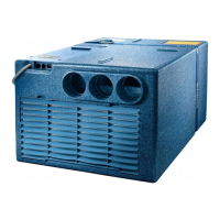
4.2 Circulated air intake
The room air to be cooled is drawn in via the air inlet on
the front of the Saphir (Fig. 4), or an additional flexible
air conditioning intake extends into the vehicle interior
(also see “7.3 Clean/change air filter with installed flexi-
ble air conditioning intake (optional)” on page16).
Fig. 4
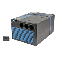
4.3 Circulated air outlets
The cooled air is distributed in the vehicle interior
through the front-mounted ducting (Fig. 5).