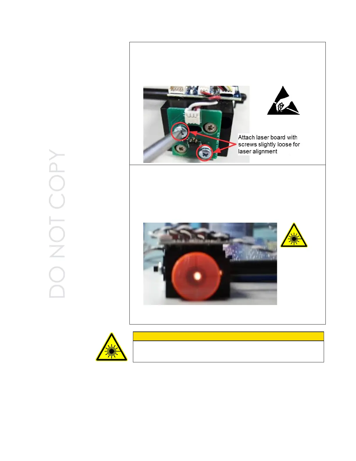
9. Remove laser diode from service kit. Install the new laser with plastic
spacer into the laser board.
10. Position the laser/laser board assembly back into the optics block
and re-attach with the two screws. Leave the screws loose for
alignment later.
11. Apply power to the unit. Adjust potentiometer on detector board until
you have a reading of 0.075 volts on the DVM. Verify that you have
laser power by looking at the alignment target and seeing a red spot.
12. Align the laser to the center cross hair of the alignment target by
moving the laser board side-to-side/up-and-down. Once it is aligned
on the cross hair, tighten the two screws holding the laser PC board
in place. Verify that the laser is still centered on cross hair.
13. Carefully remove the alignment target and place a laser power meter
in front of the beam.
C A U T I O N n
Use caution when removing alignment target and placing laser power
meter so that you do not endanger yourself or others from the laser
radiation exiting the optics block.
 Loading...