EasyManua.ls Logo

TSI Instruments 3080 Series

TSI Instruments 3080 Series
147 pages
To Next Page IconTo Next Page
Loading...
Aerosol Neutralizers
Series 3080
Electrostatic Classifiers
Operation and Service Manual
P/N 1933792, Revision K
January 2011

Table of Contents

Questions and Answers:

TSI Instruments 3080 Series Specifications

General IconGeneral
BrandTSI Instruments
Model3080 Series
CategoryMeasuring Instruments
LanguageEnglish

Summary

CHAPTER 1 Product Overview

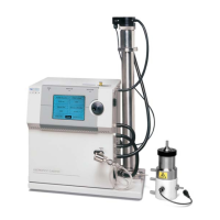
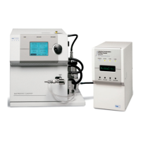
Product Description

Describes the Model 3080 Electrostatic Classifier and its components.

Applications

Outlines the various uses of the Classifier in aerosol research and sizing.

How the Classifier Operates

Explains the basic principles and components of the Classifier's operation.

System History

Details the evolution and redesign of the Classifier models.

CHAPTER 2 Unpacking and Setting Up the System

Packing List

Lists the components included in the Classifier shipping container.

Unpacking Instructions

Provides steps for safely unpacking and preparing the instrument.

Moving the Instrument

Offers guidance on safely lifting and transporting the instrument.

Mounting the Instrument

Details requirements and methods for securing the instrument.

Ventilation Requirements

Specifies necessary clearances for proper airflow and cooling.

Power Connection

Explains how to connect the instrument to a power source.

Analog Input

Describes the analog input connector for external control signals.

Connecting a Computer

Provides information on establishing computer communication.

Installing the Kr-85 Bipolar Charger

Guides the installation of the Kr-85 bipolar charger.

Installing an Impactor

Details the process of attaching and configuring the impactor accessory.

Installing Model 3081 Long DMA

Instructions for mounting the Model 3081 Long DMA.

Long DMA Mounting

Describes the quick-connect bracket for DMA mounting.

Side-Support Bracket

Explains the use of a side-support bracket for vibration environments.

Tubing

Details tubing connections for the Long DMA.

Installing Model 3085 Nano DMA

Instructions for mounting the Model 3085 Nano DMA.

Nano DMA Mounting

Describes the quick-connect bracket for Nano DMA mounting.

Tubing

Details tubing connections for the Nano DMA.

Dual Blower Mode

Explains tubing configuration for the Nano DMA in dual blower mode.

High-Voltage Connection

Provides instructions for connecting the DMA high-voltage cable.

CHAPTER 3 Controls, Indicators, and Connectors

Front Panel

Identifies main components on the front panel: display, knob, LEDs.

Indicators

Describes the Power, Sheath Flow, and High Voltage status LEDs.

Neutralizer Chamber

Location for installing the Aerosol Neutralizer.

Back Panel

Details power and data connections on the back panel.

AC Power Connector

Connector for supplying AC power to the instrument.

DC Power Input

Connector for DC power input, typically from external sources.

Serial Port

RS-232 serial connection for computer communication.

DC Power Out

Connector to power external auxiliary devices.

Analog Input

BNC connector for controlling HV with external analog signal.

Side Panel

Contains plumbing and high-voltage connections.

Polydisperse Flow Fitting

Connection for aerosol exiting the neutralizer.

Exhaust Flow Fitting

Fitting for bypass air or sheath air exiting the Classifier.

Bypass Flow Fittings

Fittings for bypass flow connections.

Excess Flow Fitting

Fitting for excess air exiting all DMAs.

Sheath Flow Fitting

Fitting for sheath air connections to DMAs.

Impactor HighLow

Fittings for connecting pressure transducer to impactor.

High Voltage Out for DMA Only

Specialized connector for HV supply to DMAs.

Internal Components

Overview of the instrument's internal parts.

System Description

Describes the Classifier's subsystems and their configuration.

Impactor

Function and mounting of the impactor accessory.

Sheath Flow Controller

Maintains constant flow through the sheath loop.

Bypass Flow Controller

Maintains constant flow through the bypass path.

Neutralizer

Provides charge distribution on aerosol entering DMA.

High-Voltage Controller

Controls the high voltage supplied to the DMA.

CHAPTER 4 DMAs: Using Different Models with the Classifier

Model 3081 Long DMA

Description and features of the Model 3081 Long DMA.

Model 3085 Nano DMA

Description and features of the Model 3085 Nano DMA.

CHAPTER 5 Operating the Classifier

Display and Menus

Explains interaction with the Classifier via control knob and LCD.

Menu

Details the main menu options for setting Classifier parameters.

Sheath Flow Rate

Allows setting the sheath flow rate for different modes.

Bypass Flow Rate

Allows setting the bypass flow rate, disabled in dual blower mode.

DMA Model

Selection of the DMA model for parameter configuration.

Impactor

Selection of the impactor nozzle installed on the Classifier.

Cabinet Temperature

Displays internal cabinet temperature for troubleshooting.

Power-Up With

Controls instrument startup settings.

Display Brightness

Adjusts LCD display brightness.

Flow Calibration

Accesses menus for calibrating sheath, bypass, and impactor flows.

Diagnostic

Toggles between normal and diagnostic display modes.

Firmware Version

Displays the current firmware version.

DMA-Voltage

Sets the rod voltage to control particle size.

Particle Diameter

Allows direct setting of particle diameter for size selection.

Multifunction Pane

Displays secondary read-only information.

Impactor

Describes impactor function and nozzle selection.

Sheath Air Flow Controller

Manages sheath air flow for optimal Classifier performance.

Neutralizer

Explains the role of the neutralizer in particle charging.

High-Voltage Controller

Details the precise control of high voltage for DMA operation.

Differential Mobility Analyzer

Instructions for selecting the installed DMA model.

CHAPTER 6 Maintenance and Service

Periodic Maintenance

Suggests maintenance tasks and schedules for proper performance.

Cleaning the Impactor

Step-by-step instructions for cleaning the impactor.

Cleaning the Long DMA Electrodes

Procedure for cleaning the inner rod and outer tube of the Long DMA.

Cleaning the Long DMA Dacron Screen

Procedure for cleaning the Dacron screen on the Long DMA.

Cleaning the Nano DMA Electrodes

Procedure for cleaning the inner rod and outer tube of the Nano DMA.

Cleaning the Nano DMA Dacron Screen

Procedure for cleaning the Dacron screen on the Nano DMA.

Cleaning Kr-85 Bipolar ChargerNeutralizer

Instructions for cleaning the Kr-85 Bipolar Charger/Neutralizer.

Replacing the Filter Cartridges

Guide for replacing the instrument's filter cartridges.

Flowmeters

Information on flowmeter maintenance and recalibration.

Replacing the EPROM

Procedure for replacing the EPROM chip.

Technical Contacts

Contact information for technical support.

Returning the Classifier for Service

Procedures for returning the instrument for service or repair.

CHAPTER 7 Troubleshooting

Detecting Particles When the Collector-Rod Voltage is Not Switched on

Diagnosing particle detection issues with collector-rod voltage off.

Testing for Leaks

Procedure for performing leak tests on the airflow system.

Isolating Leaks

Steps for identifying and repairing air leaks in the system.

APPENDIX A Model 3080 Specifications

APPENDIX B Theory of Operation

History

Background on the development of electrical mobility techniques and DMAs.

Impaction Theory and Operation

Explains the principles of inertial impaction for particle size separation.

Electrostatic Classifier

Describes the purpose and operation of the electrostatic classifier.

Charging Theory

Explains particle charge distribution models and calculations.

Particle Mobility Theory

Defines particle electrical mobility and its relationship to size.

Selected References

Lists relevant scientific papers and publications.

APPENDIX C Using Serial Data Commands

Making Connection

Instructions for connecting a computer to the Classifier's serial port.

Pin Connectors

Details the pinout and signal connections for the serial port.

Baud Rate

Specifies the communication baud rate setting.

Parity (7-Bits Even)

Explains the parity setting for data transmission.

Commands

Overview of ASCII-based commands for Classifier control.

Command Quick Reference

Provides a quick reference for serial commands.

Troubleshooting Input

Troubleshooting guide for serial command issues.

Definitions of Read Commands

Defines available read commands and their responses.

Read Pressure

Command to read various pressure values from the Classifier.

Read Flow Rates

Command to read current flow rates in the system.

Read Temperature

Command to read sheath and cabinet temperatures.

Read User Settings

Command to retrieve front panel settings.

Read Measured Values

Command to retrieve measured instrument values.

Read Firmware Version

Command to read the instrument's firmware version.

Read Model Name

Command to read the instrument's model name.

Read On Time

Command to read the accumulated operation time.

Read Flags

Command to read the status of various instrument flags.

Definitions of Combined Set Commands

Defines commands for setting various instrument parameters.

Set Particle Diameter

Command to set the desired particle diameter.

Set Voltage Mode

Command to set the voltage control mode.

Set High Voltage

Command to set the DMA high-voltage value.

Set Flow Mode

Command to set the sheath blower mode (single/dual).

Set Sheath Flow Rate

Command to set the sheath flow rate.

Set Bypass Flow Rate

Command to set the bypass flow rate.

Set Flow Calibration Algorithm

Command to select the flow calibration algorithm.

Set Flow Calibration Table

Command to set flow calibration table data.

Set Flow Calibration Table Correct

Command to confirm flow calibration table correctness.

Set or Read Impactor Serial Number

Command to set or read impactor serial numbers.

Set Offset Bit Value of Flow Sensor

Command to set flow sensor offset values.

Set Sheath Flow Calibration Parameter A

Command to set sheath flow calibration parameter A.

Set Sheath Flow Calibration Parameter B

Command to set sheath flow calibration parameter B.

Set Calibration Bypass Parameter A

Command to set bypass flow calibration parameter A.

Set Calibration Bypass Parameter B

Command to set bypass flow calibration parameter B.

Set Calibration Impactor Parameter A

Command to set impactor calibration parameter A.

Set Calibration Impactor Parameter B

Command to set impactor calibration parameter B.

Set Auxiliary Output

Command to set auxiliary output voltage.

Set DMA Parameter

Command to set various DMA parameters.

APPENDIX D Classifier Calibration

Calibration Software Setup

Instructions for installing the calibration software.

Using the Calibration Software

Guide to using the calibration software interface.

Sheath-Air Calibration

Procedure for calibrating the sheath air flow.

Bypass-Air Calibration

Procedure for calibrating the bypass air flow.

Impactor Calibration

Procedure for calibrating the impactor flows.

Working with Calibration Files

Describes how to manage calibration files (Save, Load, Print).

Related product manuals