Unpacking and Setting up the System 2–11
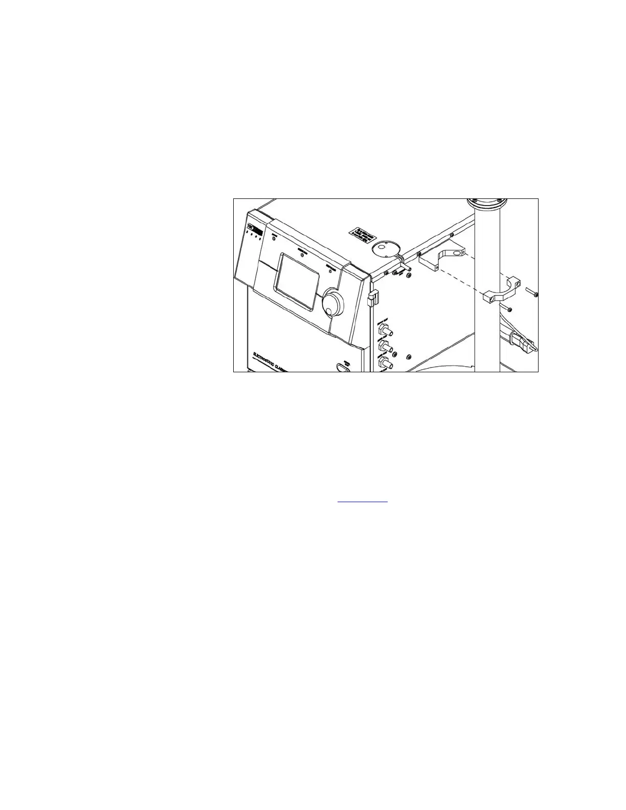
2. Install the bracket on the side of the cabinet. If the DMA is
already mounted at the base, simply pull the DMA column away
from the side of the cabinet enough to install the bracket (the
cabinet base is somewhat flexible).
3. Install the DMA with the clamp and two 6-32 × 1-inch screws
(the high-voltage cord should be routed between the clamp and
bracket—but, do not pinch the cable—it should move freely).
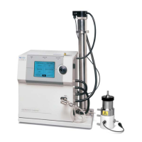
Figure 2-8
Installing the Long DMA Side-Support Bracket
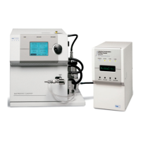
Tubing
The Long DMA requires tubing to carry aerosol and sheath air
between the Classifier and the DMA. For the Long DMA, two
internal blowers are connected in series to provide clean sheath air
up to 15 L/min (See Chapter 5
for more details). Refer to Figure 2-9
and Table 2-3 as you follow the steps listed below to install the
DMA tubing:
1. The accessory kit contains flexible, conductive tubing that
allows you to quickly configure the Classifier for use. Cut
appropriate lengths of tubing as listed in Table 2-3.
2. Connect tube #1 from the Classifier port marked
POLYDISPERSE FLOW to the DMA port marked
POLYDISPERSE FLOW.
3. Connect tube #2 from the Classifier port marked SHEATH
FLOW to the DMA port marked SHEATH FLOW.
4. Connect tube #3 from the Classifier port marked BYPASS FLOW
to the DMA port marked EXCESS FLOW.
5. Connect tube #4 from the Classifier port marked EXHAUST
FLOW to the Classifier port marked EXCESS FLOW.
 Loading...