Do you have a question about the Tunaylar Load Line 2 and is the answer not in the manual?
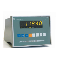
Visual layout and components of the device's front interface.
Explains the purpose and operation of each button on the front panel.
Describes the meaning of various status lights and symbols on the display.
Configuration of general operational parameters like purpose of use and interval modes.
Detailed settings for tracking, zeroing, filters, and tare functions.
Settings for capacity, decimal points, weighing units, and overload.
Methods for calibrating the device with or without weights, and gravity adjustment.
Configuration for communication ports, baud rates, and data transmission.
Settings for output operating types, input assignments, and application modes.
Configuration for printer settings like minimum load, format, and fields.
Settings for enabling, configuring, and calibrating analog output signals.
Options for internal count display and calibration value display.
Options for exiting menus, saving changes, or exiting without saving.
Function to view and change the current date.
Function to view and change the current time.
Enables and configures the piece counting functionality for items.
Enhances display sensitivity by multiplying readings by ten for a short duration.
View and print all stored weighing records from the alibi memory.
Deletes all records from alibi memory, freeing up space.
Details the data package structure for continuous serial data transfer.
Describes standard data transmit shapes for gross and net weight.
Configuration and data structure for master-slave communication modes.
Wiring diagrams and pinouts for connecting load cells (6-wire and 4-wire).
Pinout and connection diagrams for RS232 (COM1, COM2) and RS485.
Wiring details for RS422/485 serial communication, including optional configurations.
Pinout diagram for the optional analog output connection.
Diagrams illustrating the electrical connections for logic inputs and outputs.
Diagram and description for connecting the device's power supply.
| Brand | Tunaylar |
|---|---|
| Model | Load Line 2 |
| Category | Accessories |
| Language | English |