44
10.1 Load Cell Connection :
The load cell cable must not be channelled with other cables (i.e. outputs connected to
remote switches or power supply wires), but must follow its own route.
Any cable extensions must be carefully shielded, respecting the colour codes and using
the
same type of wire as that supplied by the manufacturer. The extension connections
must be
soldered or connected through support terminal blocks or the joint block
supplied separately.
The load cell wire must not have more conductors than those effectively used (4 or 6). In
the case of a 6-conductor wire, of which only 4 are used ( excitation + and
-
, signal + and
-), connect the sense + and -wires to the respective polarities of the excitation wires.
A maximum of eight 350-
ohm load cells can be connected to the instrument in parallel.
The load cell
excitation voltage is 5 Vdc and is protected against a temporary short
circuit.
6 Wire:
PIN NO DESCRIPTION SIGNAL -
SIGNAL -
EXCITATION +
EXCITATION +
SENSE +
SIGNAL +
SIGNAL +
SENSE -
EXCITATION -
EXCITATION -
CABLE
CONNECTION
1 + SUPPLY + SUPPLY
2 + SENSE + SENSE
3 + SIGNAL + SIGNAL
4 - SIGNAL - SIGNAL
5 - SENSE - SENSE
6 - SUPPLY - SUPPLY
SHLD BODY BODY
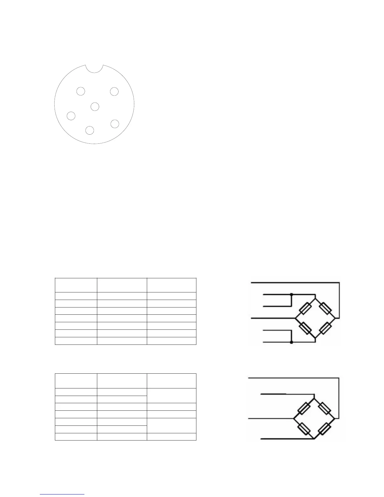
4 Wire:
PIN NO DESCRIPTION CABLE
CONNECTION
1 + SUPPLY
2 + SENSE
+ SUPPLY /
+ SENSE
3 + SIGNAL + SIGNAL
4 - SIGNAL - SIGNAL
5 - SENSE
6 - SUPPLY
- SENSE /
- SUPPLY
SHLD BODY BODY
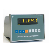
5
1
6
3
4
2
KM.LL2E.002