47
10.5 Inputs / Outputs
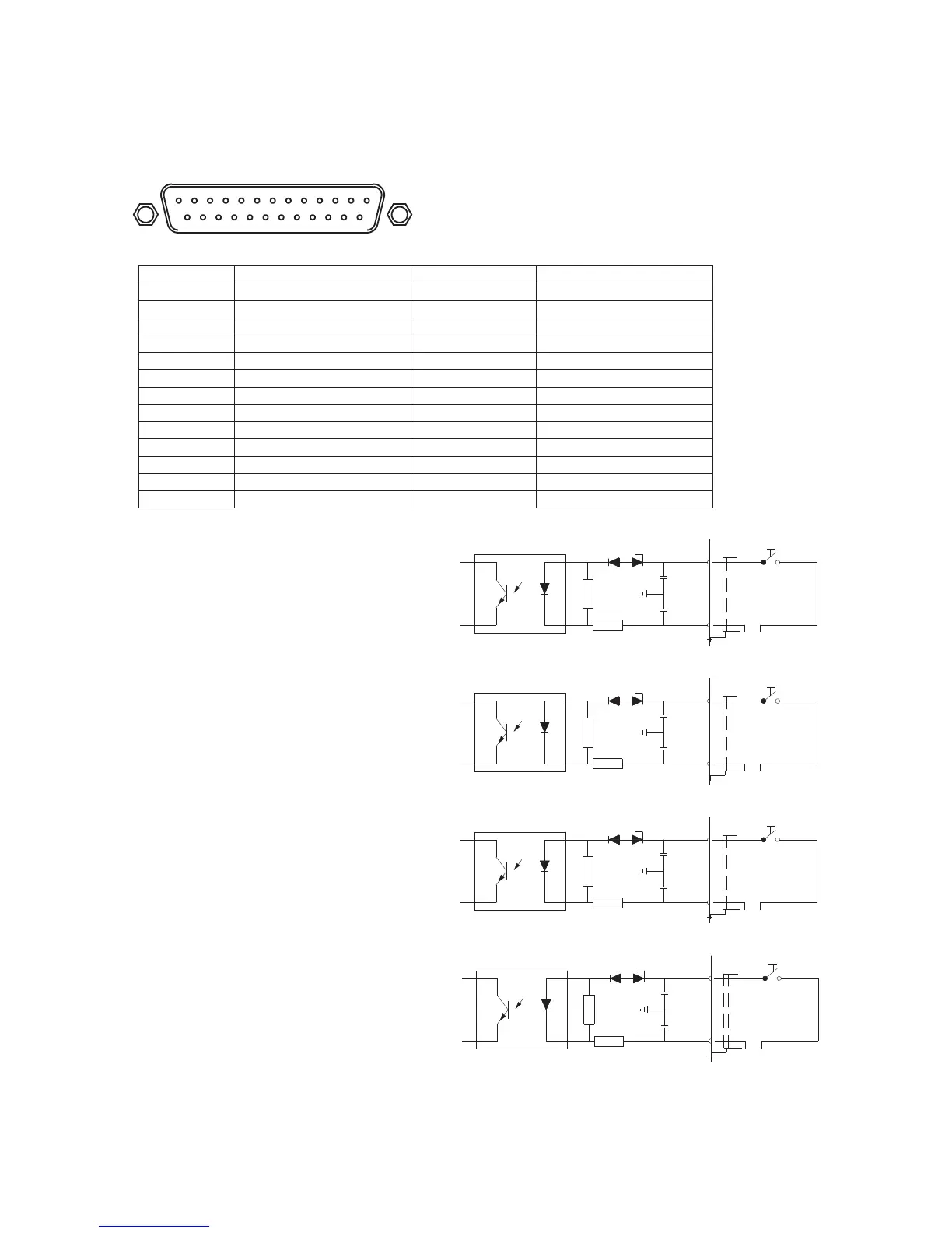
PIN NO DESCRIPTION PIN NO DESCRIPTION
1 OUT 1A 14 0VDC
2 COM 15 INPUT 1C
3 OUT 1B 16 INPUT 1D
4 OUT 2A 17 INPUT 2C
5 COM 18 INPUT 2D
6 OUT 2B 19 INPUT 3C
7 OUT 3A 20 INPUT 3D
8 COM 21 INPUT 4C
9 OUT 3B 22 INPUT 4D
10 OUT 4A 23 -
11 COM 24 -
12 OUT 4B 25 -
13 +12VDC SHLD BODY
Inputs:
The logic inputs are electrically isolated
from the instrument through opto-isolators.
- Use the shortest possible connection
wire.
The inputs are active when a voltage of 5
Vdc is applied (PNP logic).
In order to activate a logic input, it is
necessary to close the relative terminal
supplied by external power.
113
14
25
+5 V
22
-
+5 V
20
21
-
19
+5 V
+5 V
18
-
17
16
-
15
KM.LL2E.002