Do you have a question about the turck FEN20-4IOL and is the answer not in the manual?
Identifies the intended audience and required qualifications for reading the manual.
Defines the meaning of symbols like DANGER, WARNING, CAUTION, NOTICE, and NOTE.
Lists supplementary documents like data sheets and declarations available online.
Provides contact information for suggestions or missing information in the manual.
Specifies the IO-Link master module model covered by these instructions.
Lists the items included in the product package.
Details the EU directives the device complies with, such as EMC and RoHS.
Provides contact details and support resources for Turck.
Specifies the product's design for industrial areas and its intended applications.
Outlines essential safety notes for personnel, regulations, and device security.
Lists key characteristics like point-to-point connection and data transmission methods.
Explains the interconnection of IO-Link masters and devices.
Describes the digital point-to-point communication between master and device.
Details the available operating modes: IO-Link mode and Standard I/O mode.
Explains the IO-Link communication process, speeds, and response times.
Describes how devices function as digital sensors or actuators in SIO mode.
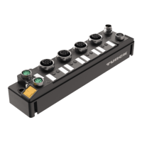
Provides a visual overview and physical dimensions of the FEN20-4IOL module.
Lists key properties such as housing, protection class, and multiprotocol support.
Explains the module's role in connecting IO-Link devices to control systems.
Details multiprotocol technology and IO-Link channel configurations.
Step-by-step guide for attaching the device to a flat mounting plate.
Instructions for installing the device onto a standard TS35 DIN rail.
Details on grounding the device and its shielding connections.
Instructions for connecting the device to an Ethernet network via RJ45 sockets.
Guide for wiring the device to its power source using the terminal connector.
Steps for connecting IO-Link devices and digital sensors/actuators.
How to set the device IP address using Turck Service Tool or other methods.
Procedure for integrating IO-Link devices compatible with V1.0 specification.
Procedure for integrating IO-Link devices compatible with V1.1 specification.
Steps for integrating the device into a PROFINET network.
Explanation of the PROFINET IO device model and GSDML file usage.
How to set the device name and IP address within a PROFINET network.
Example of connecting the device to a Siemens PLC using TIA Portal.
Instructions for installing the GSDML file for Siemens TIA Portal integration.
Steps to add and connect the device within the TIA Portal environment.
Procedure for assigning a unique name to the device in PROFINET.
Guide for configuring the device's IP address within the TIA Portal software.
How to configure IO-Link ports and device functions for PROFINET.
Steps to establish an online connection between the device and the PLC.
Instructions for commissioning the device using the Modbus TCP protocol.
Details the register mapping for accessing device data via Modbus TCP.
Guide for commissioning the device within an EtherNet/IP network.
Lists standard features supported by EtherNet/IP, like DLR and QuickConnect.
Example of connecting the device to a Rockwell PLC using EtherNet/IP.
Steps to add device entries from catalog files into RSLogix.
How to configure module name, IP address, and connection parameters in RSLogix.
Guide to parameterizing the device via controller tags in RSLogix.
Steps to establish an online connection with the PLC using RSLogix.
How to access and read process data from controller tags in RSLogix.
Details module, IO-Link port, and VAUX1 monitoring parameters.
Guides on swapping process data for different fieldbus structures.
Configuration parameters specific to PROFINET device and I/O channels.
Explains acyclic data transfer using IO-Link CALLs for master and devices.
Details port functions and index usage for the IO-Link master.
Interpreting process input data bits for basic, IO-Link, and diagnostic information.
Instructions for controlling digital outputs and VAUX1 supplies.
Explanation of the meaning of different LED states for BUS and Ethernet ports.
Overview of diagnostic messages including overcurrent, IO-Link, and master diagnostics.
Details the bits within the status word for device communication and diagnostics.
Explains the diagnostic telegram structure and the meaning of diagnostic bits.
Maps PROFINET diagnostic error codes to specific hardware and port issues.
Guide on utilizing data storage for parameter synchronization between master and device.
Explains the bidirectional synchronization of parameters when data storage is activated.
Configures data storage to use the device's data set as the reference.
Configures data storage to use the master's data set as the reference.
Deactivates data storage and clears the master's parameter data memory.
Solutions for errors like digital outputs not switching or data storage issues.
Instructions for updating the device firmware using PACTware.
Information regarding device repair limitations and return procedures.
Guidelines for environmentally correct disposal of the equipment.
| Brand | turck |
|---|---|
| Model | FEN20-4IOL |
| Category | Control Unit |
| Language | English |