Do you have a question about the turck TBEN-S Series and is the answer not in the manual?
Instructions aimed at qualified personnel for device operation and maintenance.
Explains symbols used in the instructions for clarity and safety.
Lists additional relevant documents available online for further information.
Provides contact information for submitting suggestions for improving the instructions.
Identifies applicable devices and firmware versions for these instructions.
Lists items included in the product's scope of delivery.
Lists applicable EU directives for the product.
Describes Turck's support services and product database availability.
Defines the intended use of the devices in industrial areas and protocols.
Provides general safety guidelines for device assembly, operation, and maintenance.
Safety notes for devices used in explosion-protection circuits.
Specifies ATEX and IECEx requirements for safe use in Ex areas.
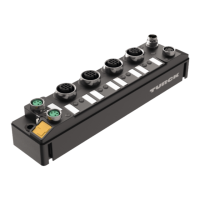
Provides a visual overview of device dimensions and connector layouts.
Describes the device's LED indicators for status monitoring.
Lists key features and characteristics of the device.
Explains the device's multiprotocol capabilities and operating modes.
Details the supported Ethernet protocols and their detection methods.
Describes extended functions for digital modules like filters and counters.
Explains the FLC function for on-device logic processing.
Describes the BEEP technology for network expansion.
Illustrates different Ethernet network configurations.
Specifies the maximum number of modules in an Ethernet daisy chain.
Lists accessories for mounting, connecting, and parameterizing the devices.
Safety instructions for mounting devices in hazardous areas.
Instructions on how to combine TBEN-S modules for mounting.
Details on mounting TBEN-S modules on a mounting plate.
Instructions for mounting modules on a DIN rail.
Steps for attaching modules to a mounting plate.
Procedure for mounting modules on a DIN rail.
Guidelines for mounting devices in outdoor environments.
Explains grounding concepts and wiring diagrams for the device.
Presents circuit diagrams and shielding concepts for module variants.
Details shielding concepts for fieldbus and I/O levels.
Describes grounding methods for I/O and fieldbus levels.
Explains grounding when mounting on a DIN rail.
Describes grounding when mounting on a mounting plate.
Safety precautions for connecting devices in hazardous areas.
Instructions for connecting the device to an Ethernet network.
Details on using QuickConnect and Fast Start-Up for Ethernet connections.
Explains how to connect the device's power supply.
Describes the dual voltage supply concept for TBEN-S1 modules.
Guides on connecting digital sensors and actuators to the devices.
Instructions for connecting analog sensors and actuators.
Details on setting the device's IP address using Turck Service Tool.
Provides an overview of available parameters for digital modules.
Lists and describes parameters for digital I/O channels.
Details PROFINET-specific device and I/O channel parameters.
Explains the structure of process input data for digital modules.
Maps process input data bits for various digital modules.
Maps process input data for analog modules.
Explains process output data structure for digital modules.
Maps process output data bits for various digital modules.
Describes PROFINET IO device model and address setting.
Explains the PROFINET IO device model structure.
Details IP address assignment and device naming in PROFINET.
Explains FSU for fast PROFINET node connection.
Describes the MRP protocol for media redundancy.
Explains acyclic data exchange using Record Data CRs.
Guides on connecting devices to a Siemens PLC using TIA Portal.
Steps for installing the GSDML file in TIA Portal.
Instructions for connecting devices to the PLC in TIA Portal.
How to configure device functions in TIA Portal.
Steps to assign a PROFINET device name in TIA Portal.
Procedure for setting the IP address within TIA Portal.
Guides on setting module parameters in TIA Portal.
Steps to establish an online connection with the PLC.
Explains PROFINET data mapping.
Details on configuring devices for Modbus TCP communication.
Lists supported Modbus functions for data access.
Provides a table of Modbus registers and their meanings.
Shows data width and alignment for TBEN-S modules in Modbus.
Maps registers for TBEN-S modules in Modbus communication.
Explains the meaning of various register bits.
Describes output behavior and bus LED status during errors.
Guides on connecting devices to CODESYS PLC via Modbus TCP.
Steps to add Ethernet adapter, Modbus TCP Master, and Slave in CODESYS.
Instructions for configuring the network interface for Modbus master.
Details on setting the IP address for the Modbus TCP slave.
Steps to define input and output registers for Modbus channels.
Instructions to go online with the PLC in CODESYS.
How to read process data using Modbus TCP Slave I/O Mapping.
Details on configuring devices for EtherNet/IP communication.
Lists common features of EtherNet/IP devices.
Information on obtaining EDS and catalog files.
Explains the QuickConnect feature for fast EtherNet/IP connections.
Describes the DLR redundancy protocol for EtherNet/IP networks.
How diagnostic data is mapped into process data.
Lists standard EtherNet/IP classes according to CIP specification.
Details vendor-specific classes for device configuration.
Describes the function of the device's LED indicators.
Explains the meaning of LED indicators on TBEN-S modules.
Describes the function of channel LEDs for digital modules.
Explains the function of channel LEDs for analog modules.
Guides on evaluating diagnostic data mapped into process data.
Details diagnostic data mapping for PROFINET on TBEN-S1-8DIP.
Instructions for updating device firmware using FDT/DTM.
Procedures and requirements for returning devices to Turck.
General technical specifications including power, connectors, and system data.
Technical specifications for TBEN-S1-8DIP digital inputs.
Technical specifications for TBEN-S1-8DIP-D digital inputs.
Technical specifications for TBEN-S2-8DIP digital inputs.
Technical specifications for TBEN-S1-8DOP digital outputs.
Technical data for TBEN-S1-4DIP-4DOP digital inputs/outputs.
Technical specifications for TBEN-S1-4DXP digital inputs/outputs.
Technical specifications for TBEN-S1-8DXP digital inputs/outputs.
Technical specifications for TBEN-S2-8DXP digital inputs/outputs.
Technical data for TBEN-S2-4AI analog inputs.
Basic error values for RTD/resistance and thermocouple operation modes.
Measurement error totals for RTD/resistance and thermocouple modes.
Example calculations for operational and total measurement errors.
Technical data for TBEN-S2-4AO analog outputs.
Provides block diagrams for digital and analog modules.
| Product Series | TBEN-S |
|---|---|
| Protection Class | IP67 |
| Communication Protocols | Ethernet/IP, Modbus TCP, PROFINET |
| Digital Inputs | Up to 16 |
| Digital Outputs | Up to 16 |
| Analog Inputs | Up to 8 |
| Analog Outputs | Up to 8 |
| Housing Material | Plastic |