V04.00 | 2021/05
33
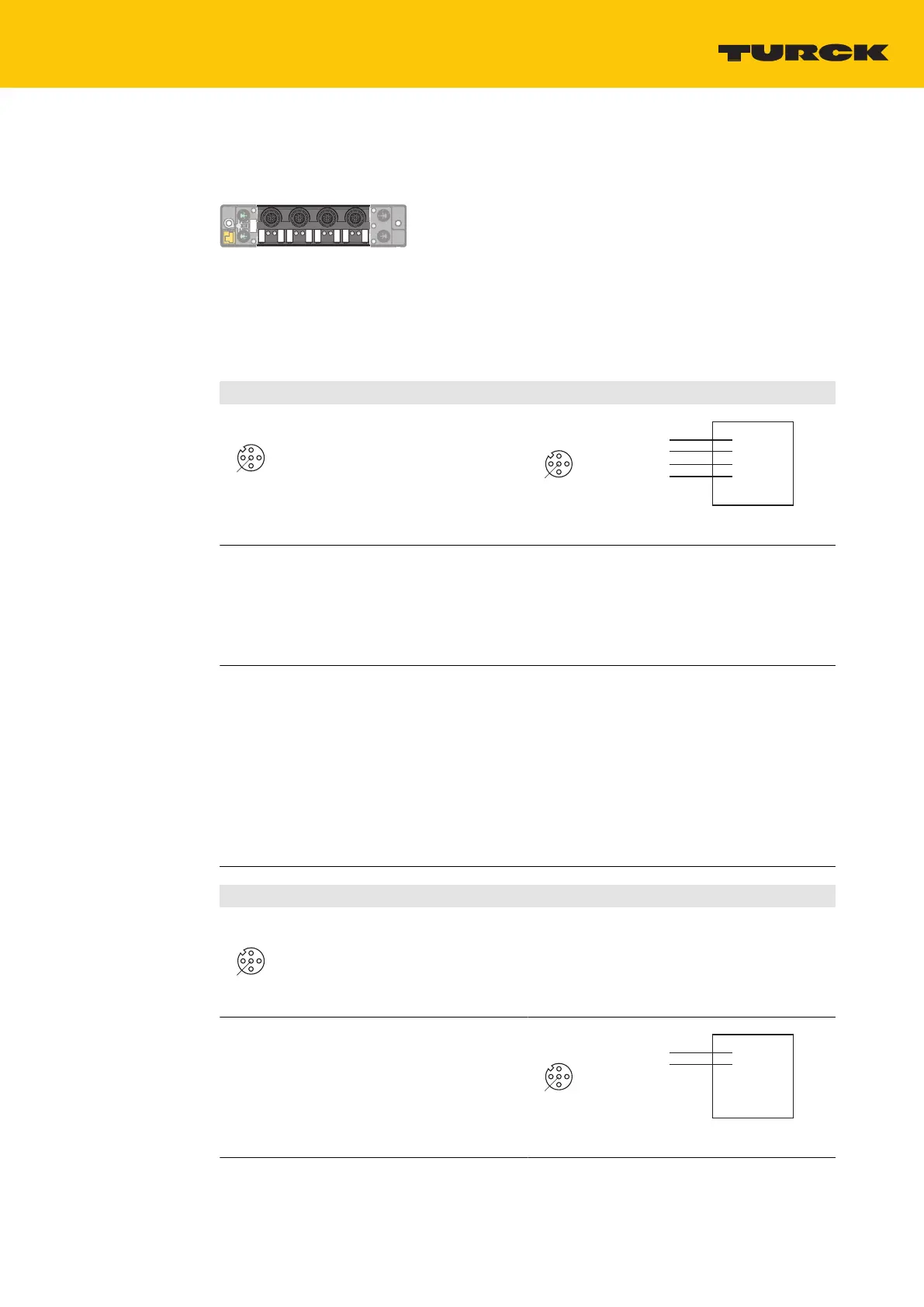
6.5 Connecting analog sensors and actuators
The devices provide 5-pin M12 connectors for connecting analog sensors and actuators.
Fig.42: M12 connector for connecting analog sensors and actuators
Connect the sensors and actuators to the device according to the pin assignment.
Seal unused slots with blind plugs.
TBEN-S2-4AI – current/voltage
Differential
4
1
3
2
5
v
1 = V
aux
1
2 = AI +
3 = GND V1
4 = AI –
5 = FE
Flange = FE
C0...C3
4
1 3
2
5
v
1 = V
aux
1
2 = AI+
3 = GND
4 = AI–
5 = FE
Flange = FE
C0…C3
+
Signal +
–
Signal –
Connection of differential signals with connection to ground:
An internal 10 kΩ pull-down resistor between AI- (pin 4) and ground (pin3) defines the com-
mon mode voltage and prevents the common mode voltage from drifting away from ground.
Compensation currents via AI- (Pin 4) might influence measured value.
Parameterize TBEN-S2-4AI as follows:
Current wiring type = differential
Connection of differential signals without connection to ground:
Connection of sensors with a high output impedance (e.g. unbuffered Wheatstone bridge).
The absolute potential can float against the measurement range limits (common mode
voltage max. ±18 V). This will with effect of reduced relative range. This may lead to the fact
that no measurement is possible.
Take precautions to prevent the common mode voltage from drifting away from
ground.
Parameterize TBEN-S2-4AI as follows:
Current wiring type = differential without ground
a The internal 10 kΩ pull-down resistor is deactivated.
Single ended
1 = V
aux
1
2 = AI +
3 = AI –/GND V1
4 = n.c.
5 = FE
Flange = FE
C0...C3
4
1
3
2
5
v
Connection of sensors with common ground
A- and GND are internally bridged.
Parameterize TBEN-S2-4AI as follows:
Current wiring type = single ended
2-wire connection
4
1 3
2
5
v
1 = V
aux
1
2 = AI+
3 = GND
4 = AI–
5 = FE
Flange = FE
C0…C3
+
Signal +

 Loading...