Manual 2007 Rev B p/n 2007
6
Refer to specifi c data sheets for fl ow capacities
and vacuum capacities.
OTE: N See Figure 4-2 on page 7 for proper
rotation and orientation in inlet and
discharge.
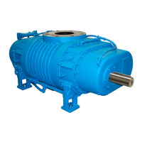
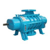
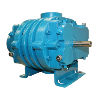
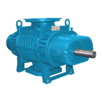
Tuthill Vacuum & Blower Systems model 7000
rotary lobe blowers are positive displacement type
blowers, whose pumping capacity is determined
by size, operating speed, and differential pressure
conditions. Blowers employ rotors rotating in
opposite directions within a housing closed at the
ends by end plates.
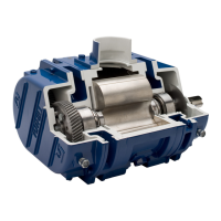
The inlet to the discharge is sealed with operating
clearances that are very small. Internal lubrication
is not needed, as there is no moving contact.
Clearances between the rotors during rotation are
maintained by a pair of accurately machined helical
timing gears, mounted on the two shafts extended
outside the air chamber. The intermeshing rotary
lobes are designed to rotate and trap air or gas
between each rotor and the housing. As the rotor
lobes rotate past the edge of the suction port, the
trapped air or gas is essentially at suction pressure
and temperature. Since the blower is a constant
volume device, the trapped air remains at suction
pressure until the leading rotor lobe opens into the
discharge port. The close clearances between the
rotors inhibit back slippage of the trapped volume
from between the rotors and the trapped volume
is forced into the discharge piping. Compression
occurs not internal to the blower but by the amount
of restriction, either downstream of the blower
discharge port or upstream of the blower inlet port.
Figure 4-1 illustrates the air movement within the
machine. The air moves not between the rotors
but between the rotors and the side of the housing.
Also, the machine is bi-directional, meaning that
the direction of rotation of the blower can make
either side the inlet or discharge. See also Figure
4-2 on page 7.
Never attempt to control capacity by means of a
throttle valve in the intake or discharge piping.
This will increase the power load on the drive
system, will increase operating temperatures,
and can overload and/or seriously damage the
blower. Likewise, if a possibility exists that fl ow
to the blower inlet may be cut off during normal
operation of a process, install an adequate vacuum
relief valve near the blower. A pressure-type relief
valve in the discharge line near the blower is also
recommended for protection against cutoff or
blocking in this line. Use check valves on each
blower when more than one blower is connected to
a discharge line.
When a belt drive is used, blower speed, it is
possible to adjust blower speed to obtain the
desired capacity by changing the diameter of one or
both sheaves, or by using a variable-speed motor
pulley. In a direct-coupled arrangement, a variable-
speed motor or transmission is required, or excess
air or gas may be blown off through a manually
controlled unloading valve and silencer. Gas units
can use bypasses, but some applications may
require additional cooling. If there is a large volume
of high-pressure air or gas downstream of the
blower, a check valve in the piping downstream of
the blower will protect the blower from overspeeding
in a backward direction upon shutdown.
Consult a Tuthill Vacuum & Blower Systems sales
professional if questions arise.
DESCRIPTION
04