Manual 2007 Rev B p/n 2007
20
05
Installation
COOLING WATER CONNECTIONS
AND SPECIFICATIONS — COOLING
COILS (OPTIONAL)
WARNING
!
The cooling water pressure shall not exceed
75 psig (5.17 bar g).
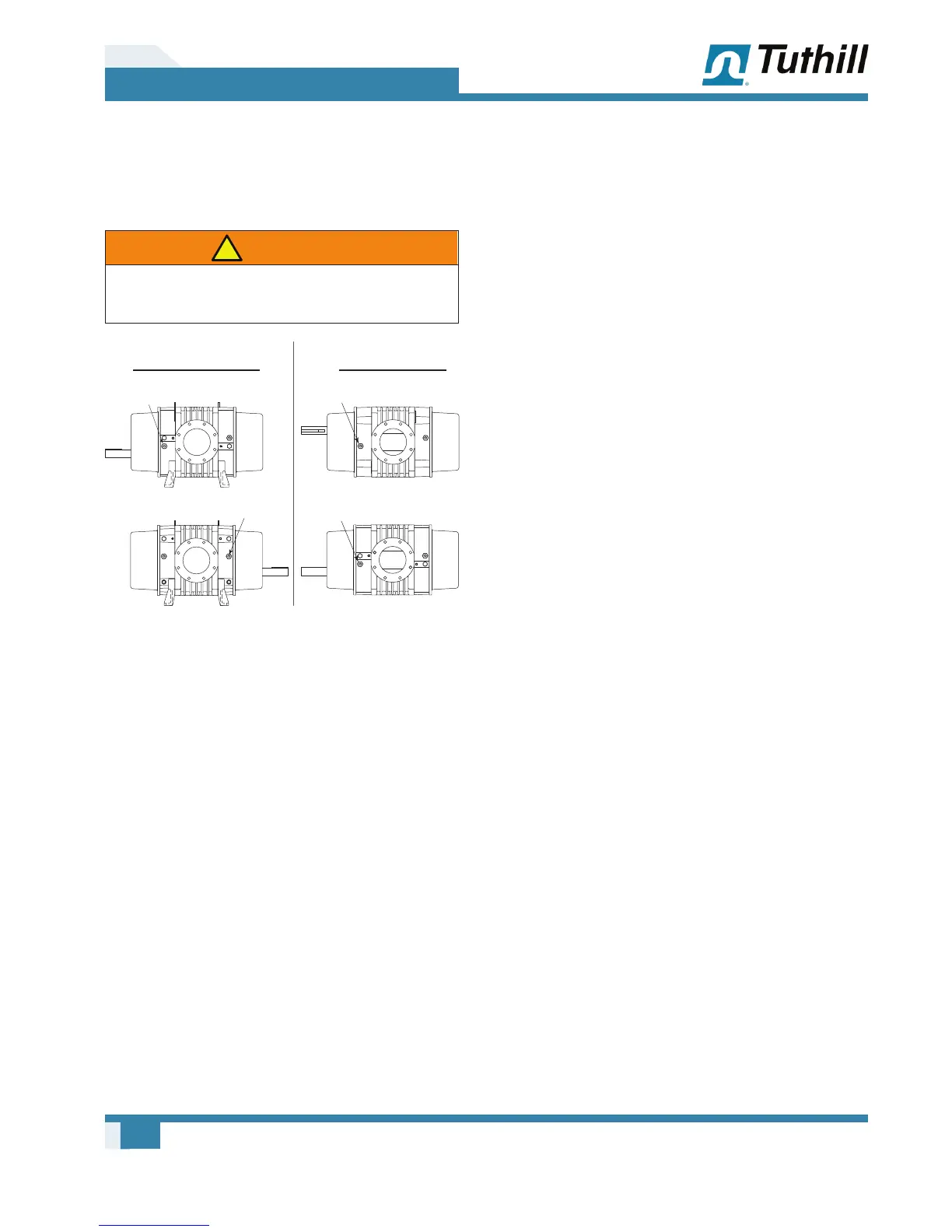
PD 7000 SERIES
HORIZONTAL FLOW
PD 7000 SERIES
VERTICAL FLOW
1/2 NPT
WATER OUTLET
(1) EA END PLATE
1/2 NPT
WATER OUTLET
(1) EA END PLATE
1/2 NPT
WATER IN
(1) EA END PLATE
1/2 NPT
WATER INLET
(1) EA END PLATE
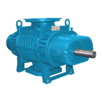
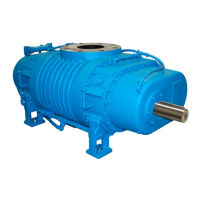
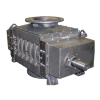
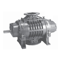
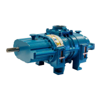
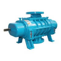
Figure 5-6 – Cooling Connections on Blowers with
Cooling Coils Option
MOTOR DRIVES
Two drive connections commonly used are direct
drive and V-belt drive.
Direct Coupled
When installing the motor directly to the blower,
align the shafts to the coupling according to the
coupling manufacturer’s instructions. Blowers
shipped with motor directly coupled and mounted
on a common base have been aligned prior to
shipment. Further alignment is normally necessary,
but be sure to check the alignment and make
adjustments if necessary prior to starting the
blower.
Coupling halves must correctly fi t the blower and
drive shafts so that only light tapping is required to
install each half. The two shafts must be accurately
aligned, A direct-coupled blower and motor must be
aligned with the two shafts not having more than
0.005 in. (13 mm) Total Indicator Reading (T.I.R.).
Make sure the face is aligned within 0.002 in.
(0.05 mm).
Establish proper gap between coupling halves
according to the coupling manufacturer’s
instructions with the motor armature. Proper
gap will minimize the chance for end thrust
on the blower shaft. Re-align and grease all
direct-coupled base-mounted blowers after fi eld
installation.
V-Belts
If the motor and blower are V-belt connected, the
sheaves on both the motor and blower shafts
should be as close to the shaft bearings as
possible. Blower sheave is not more than 1/4 in.
(6.5 mm) from the blower drive end cover. The
drive sheave is as close to the driver bearing as
possible. Take care should when installing sheaves
on the blower and motor shafts. Make sure the
face is accurately in line to minimize belt wear.
Adjust the belt tension to the to the manufacturer’s
specifi cations using a belt tension tester. Check
new belts for proper tension after 24 hours of run
time. When manufacturer data is not available,
industry guidelines are 1/64 in. defl ection for each
inch of span (0.157 mm per centimeter of span) at
8 – 10 lb (3.6 – 4.5 kg) of force in the center of the
belt.
Insuffi cient tensioning is often indicated by slipping
(squealing) at start-up. Do not use belt dressing
on V-belts. Keep sheaves and V-belts free of oil
and grease. Remove tension from belts if the
drive is to be inactive for an extended period of
time. For more specifi c information, consult the
drive manufacturer. In a V-belt drive, the blower
sheave must fi t its shaft accurately, run true, and
be mounted as close to the bearing housing as
possible to minimize bearing loads.