Manual 2007 Rev B p/n 2007
35
08
Disassembly and Reassembly
12. Mechanical face seal series: Put sealant
on the rotor housing, in the same manner as
described in step 11.
All series: Install the free end plate and
secure in the same manner as described in
step 11.
13. Mechanical face seal series: Install the seal
mating rings as was done in step 4.
As needed: Install one bearing spacer on
each shaft. This is normally not required.
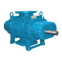
Lubricate the shafts and install roller bearings
with the inner race fl ange outward. See Figure
8-4.
HOUSING
END COVER
Figure 8-4 – Roller bearings
14. Install the oil retainer rings and cap screws.
Install the roll pin, washers, oil slinger (on the
drive rotor), lock tabs, and bolts. Bend over the
tabs.
15. Install the mounting feet with the machined
surface against the housing, and secure with
the lock washers and cap screws. Install the
lifting lugs with the cap screws.
Adjusting Rotor Interlobe Clearance
16. The driven gear is made of two pieces. The
outer gear shell is fastened to the inner hub
with four cap screws and located with two
dowel pins. A laminated shim, made up of
0.003 in. (0.076 mm) laminations, separates
the hub and the shell. By removing or adding
shim laminations, the gear shell is moved
axially relative to the inner hub. Being a helical
gear, it rotates as it is moved in or out and the
driven rotor turns with it, thus changing the
clearance between rotor lobes.
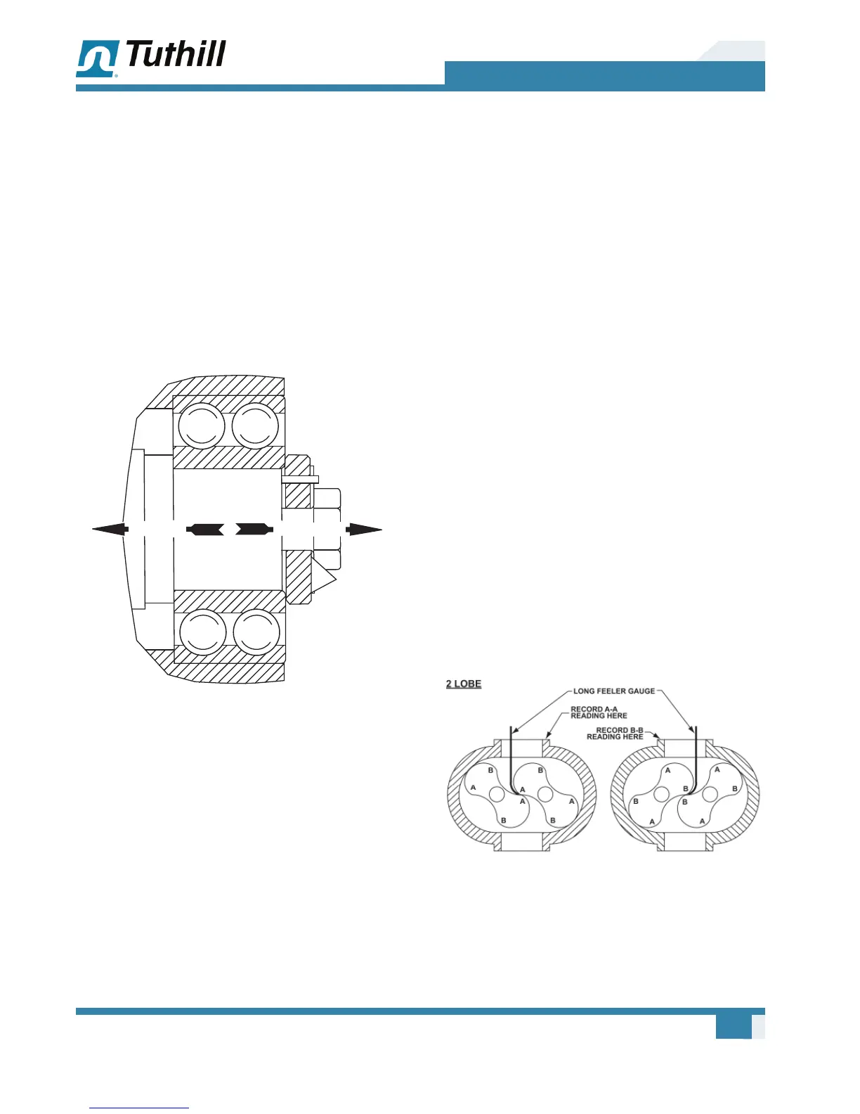
EXAMPLE: See Figure 8-4. Check the
clearance at AA (right-hand reading) and BB
(left-hand reading). If AA reading is 0.017 in.
(0.43 mm) and BB reading is 0.004 in.
(0.10 mm), by removing 0.026 in. (0.66 mm) of
shim, the AA reading should then read
0.011 in. (0.28 mm) and the BB reading should
read 0.010 in. (0.25 mm).
To determine the amount of shim to add or
remove, subtract the smaller fi gure from the
larger and multiply the result by 2.0. If the
right side reading is higher than the left side,
remove shim. If the right side reading is lower,
add shim. The fi nal readings should be within
0.002 in. (0.05 mm) of each other. When
removing the gear shell from the driven gear, it
is not necessary to remove the gear lock bolt.
Figure 8-5 – Checking Rotor Interlobe Clearance