Manual 2007 Rev B p/n 2007
34
08
Disassembly and Reassembly
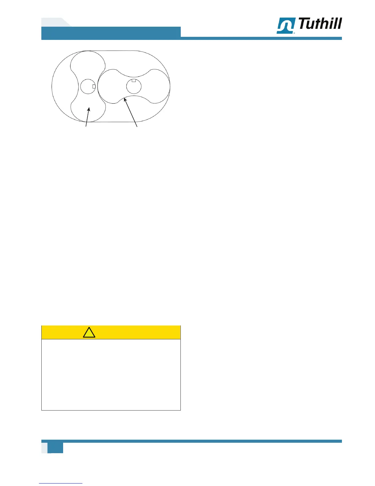
Drive
Driven
DRIVE DRIVEN
Figure 8-3 – Keyways
4. Install the gear end plate over the rotor
shafts and coming to rest on top of the rotor
lobes, being careful not to damage the seals.
Recheck the location of the oil sight glass in
relation to the drive rotor before proceeding
with the assembly.
Lab seals series only: Skip step 5. Proceed
to step 6.
5. Mechanical face seal series only: Inspect
the lapped surface of the seal mating ring to be
sure it is perfectly clean. Use a soft tissue and
cleaning agent if necessary. Place a few drops
of lubricating oil on its surface and lubricate the
O-ring. Install on the rotor shaft with the lapped
surface down. The slot must line up with the
pin in the rotor shaft. Gently press with fi ngers
to ensure compression is taking place and the
mating ring is not hung up for any reason. The
top of the mating ring should sit fl ush with the
rotor shoulder when fully seated.
CAUTION
!
Gear end bearings have fl ush ground faces
and should be installed with manufacturer
numbers up (toward gear). If no numbers
appear on either side, look for a black dot
(acid mark) on the inner race. Install with dot
up (toward gear). Do not use bearings that
have not been fl ush ground to within a .001"
(.025 mm) tolerance.
6. Coat the rotor shafts with an anti-seize
lubricant and press the bearings on the shafts.
The bearing manufacturer numbers and/or an
acid dot (inner race) should be up or toward
the gears. Use the tool shown in Figure 13-4
along with a length of 3/4”-10 × 6 in. threaded
rod, washer, and nut. Tuthill recommends the
use of a hydraulic ram with a hollow center, in
which case the threaded rod will have to be
made longer. Install the bearing retainer plates
and secure with cap screws.
7. Check the clearance between the face of the
end plate and rotor lobes. See Assembly
Clearances on page 39 for the correct
gear end clearances. If clearances are not
within specifi cations, recheck the parts to fi nd
the cause of the improper clearances before
proceeding. Install the keys in the rotor shaft
keyways.
8. Lubricate the shafts and keys, and press the
drive gear (right-hand helix) on the drive rotor.
To install the driven gear, align the reference
marks as shown in Figure 8-5. Tap the gear
with a mallet to start, and then press the gear
until seated.
OTE: N All timing gears must be used in sets as
they are matched and serially numbered.
9. Install the roll pins, washers, lock tabs, and
shaft bolts. Bend over the lock tabs.
OTE: N These bolts are structural bolts, not
standard cap screws. Therefore they have
a larger body diameter and this centers
the washers and slinger. Do not replace
with standard cap screws.
10. Remove the gear end assembly from the free
end plate, and turn over so the gears are
facing down on some wood blocking on each
side for support.
11. Mechanical face seal series: Place a small
bead of sealant around the periphery of the
housing bores but inside the bolt pattern.
Encircle the dowel pins. Install the rotor
housing and temporarily secure it to the end
plate with two cap screws and some fl at
washers. Check the clearances between the
end of the lobes and housing using a fl at bar
and feeler gauges or a depth micrometer. See
the exploded view for free end clearances.