Manual 2007 Rev B p/n 2007
36
08
Disassembly and Reassembly
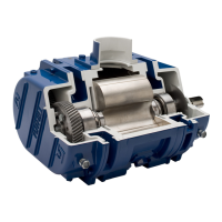
17. Install the inner race of the drive shaft roller
bearing onto the drive shaft. The fl ange side
must be inboard. See Special Tool Drawings
on page 43. Install the outer race with the
rollers into the cover bore fl ush with the inside
boss. Install the oil slingers back-to-back on
the drive shaft fl ange. Make sure both mating
surfaces are clean and free of burrs, and then
mount the drive shaft to the gear and secure
with nylok cap screws. Check the drive shaft
runout at the seal journal. Do not exceed 0.003
in. (0.08 mm) T.I.R.
18. Remove the temporary cap screws from the
gear end of the housing, and place a bead of
silicone around the periphery of the end plate.
Encircle the dowel pins. Install the cover and
cap screws. Tuthill recommends using two
1/2”-13 threaded rods as guide screws.
Drive Shaft Seal Assembly
19. On blowers with drive shaft lip seal: Press
the drive shaft lip seal into the seal housing.
This is a double-lip seal; pack with grease.
Install the O-ring and assemble to the cover
with hex cap screws.
On blowers with integral drive shaft
mechanical face seal:
a. Install the O-ring into the seal housing,
and press in the stator portion of the
mechanical seal. See Special Tool
Drawings on page 43. Clean the face
of the carbon and mating ring with soft
tissue and acetone. Install the O-ring.
b. Lubricate the O-ring in the I.D. of the
mating ring and carefully slide onto the
drive shaft with the slot up and seat
against the shoulder. Do not use any
tools. The lapped surface should be facing
outward.
c. With the set screws in place, install the
mating ring retainer while aligning the pin
with the slot in the mating ring. Secure to
the shaft with the set screws.
d. Install the nose piece lip seal adapter into
the cover bore and secure with four hex-
head screws.
20. Install the free end cover using the same
process as used for the gear end.