Page 54 of 102
TVL 351
ISSUE 15
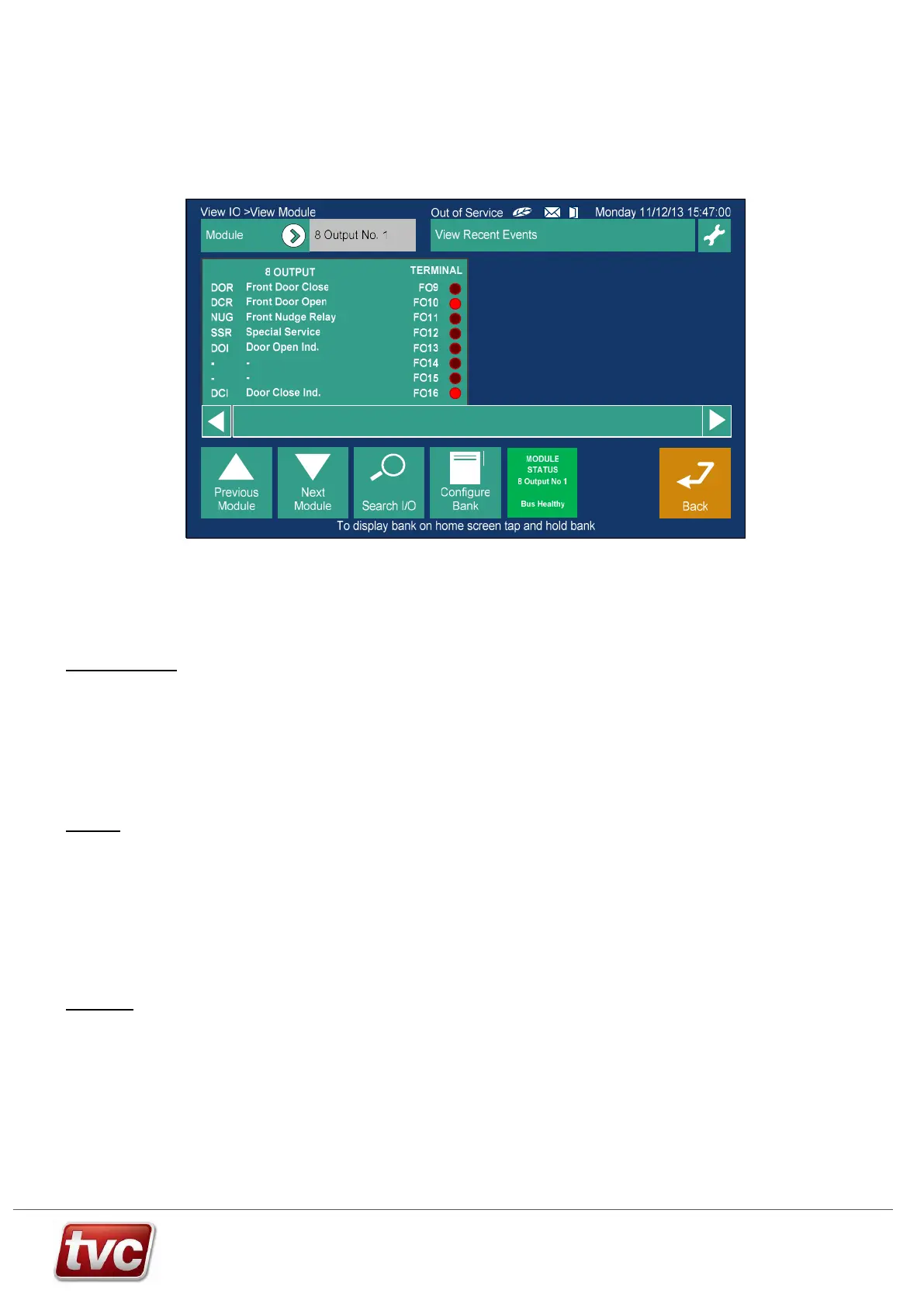
10.2. Feature Modules
4 types of feature module are available 8 way input, 8 way output, 4 way input / output and 24 way output. Up to 10 -
8 way modules, 2 - 4 I/O modules and 2 - 24 way modules can be added, this covers applications that require
interfacing to BMS systems or existing hall lanterns etc.
Feature I/O can be viewed through the MMI via the View I/O button
10.3. Serial Network - Installation Guidelines
This general guide is designed to give an outline of installation and setup of an Ethos Two serial network. Please
refer to relevant installation pages for more in depth information.
Machine Room
Install main panel. Make sure the routing of any mains or motor cables are kept away from the network cables.
Connect the car network from the trailer to terminals as shown on the panel drawings. Make sure screens from the
trailer are earthed, as the drawings show.
If fitted, connect up the shaft network to the power feed board and then if applicable connect this to the other
controllers in the group.
Once wiring has been completed and checked follow the standard Ethos Two power up routine.
Make sure all nodes are present in the view I/O screens of the MMI. All nodes can be tested by activating inputs or
call pushes and seeing the result appear on the MMI view I/O screens.
Lift Car
The car related boards may be mounted in the car push station or in the terminal box on the car top.
Wire in all car pushes and acceptance lamps plus optional features inputs and outputs as per wiring diagrams.
The car module(s) will be configured for front or rear operation. Also the call expansion boards and I/O boards as
will be configured as shown on the controller diagrams.
Connect all nodes together with supplied patch cables, as per the drawings. The final board in the chain should have
its network termination DIP’s switched on, again make sure these are only active on one node on the car / panel
network.
Plug the first board on the car top into the relevant trailer connections.
The screens from the trailer cores must be earthed at the panel end of the trailer only, as per the diagrams.
Lift Shaft
Mount optional Landing Nodes in the shaft, either in the push back boxes or in a suitable plastic box mounted close
to the push station.
Each Landing node has a unique ID this should be set as per the controller drawings, make sure the nodes are
installed at the correct landings.
Connect Landing pushes and acceptance lamps to nodes, make sure wiring is correct 3-wire system.
Connect each landing node to the next one in the shaft, using the supplied patch cables.
Connect terminator boards, if applicable, to the ends of the landing networks. Warning: a maximum of 2 terminators
should be fitted to this network in total.
Connect landing node network back to the Power Feed Board on the Ethos Two controller.