Page 88 of 102
TVL 351
ISSUE 15
Appendix F: Handwind Unit – HW03
Only components
of interest shown!
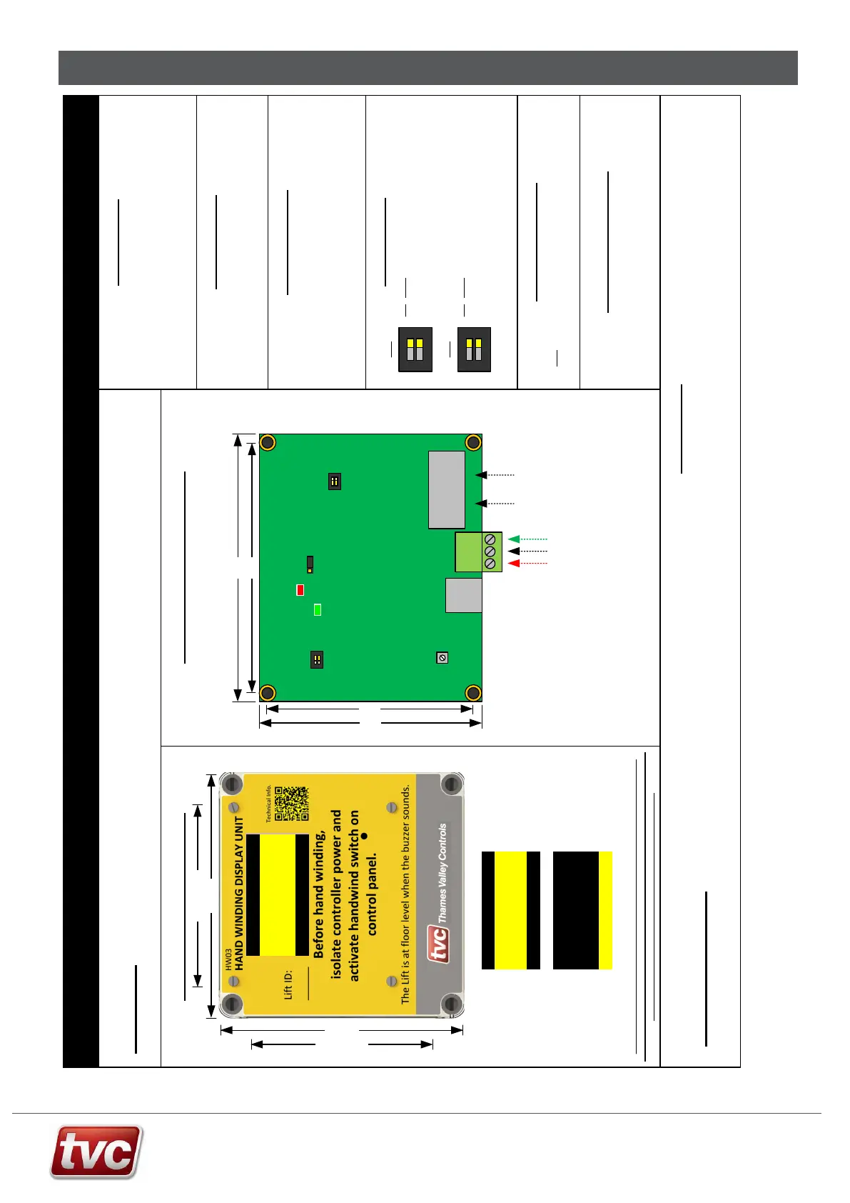
HW03 Handwind Node Board Installation Sheet
Precautions
Observe normal precautions for handling electronic devices, avoid static
electricity, dampness and extreme temperatures.
Please read this instruction sheet fully before use.
The unit is to be wired as per the relevant panel drawings.
Specification
Supply Voltage 24 V d.c.
Board Operating Current 40mA
Internal PCB Layout (Rear)
DIP Settings
DIP Name
2 Test Dip Bit 1
1 Test Dip Bit 0
Loop and Fault LED’s
The Green LED (D10) will flash every 2 seconds to signify power to node and that the
node is running.
The Red LED (D11) will light continuously for 4 seconds when the node is first powered
up. After this point the red LED signifies various fault codes. The LED will flash every 4
seconds if the node has a fault.
VOL
SW2
D10
D11
J4
ON
1 2
SW3
SW1
DIP Name
2 CAN Term
1 CAN Term
DIPs 1 and 2 on for CAN termination
These should only be set on the last
node in the network. (optional)
SW3
ON
1 2
Jumper Settings
SW2 Place Jumper in the 1-2 position for normal operation.
Volume Adjustment
The HW03 Handwind Node board comes with built in buzzer to confirm
floor level. For volume adjustment turn potentiometer R52, clockwise to
increase volume and anti-clockwise to lower the volum e.
Red Network Debug LED
1 flash every 4 secs = Node not communicating with Ethos.
2 flashes every 4secs = Node is experiencing data bus faults.
3 flashes every 4 secs = N ode has stopped transmitting due to bus faults.
4 flashes every 4 secs = N ode has stopped transmitting or r eceiving from the data bus
91mm
97mm
CAN Network
from Controller
ON
1 2
OFF
SW1
82mm
88mm
24V
0V
ET
24V
0V
ET
ON
1 2
Both DIPs off = Normal / Running Mode.
DIP 1 on only = Demo Mode.
DIP 2 on only = Functional Test.
DIP 1 and 2 on = Display Test.
R52
Level Legends
The level legends can be adjusted via the Ethos Two MMI.
Press the “Indicators and Speech” button on the main screen and then
select Floor Legend, use the index arrow s to select the floor and then edit
the floor legend characters. The character l imit is 2.
Introduction
The HW03 Handwind unit is a unit for displaying lift floor level for handwinding purposes. The unit should be mounted close to the lift machine so the person
handwi nding has visibility of the floor position w hen moving the lift.
Caution:- Electrically isolate the lift controller if handwinding is to be carried out. The unit will display Handwind Mode when isolated.
In Door Zone
Handwind Mode
= G
Lift on
Handwind
Buzzer will sound at
floor level.
Normal
Operation
HW03 Modes of Operation
Screen Saver:- If no activity is seen from the lift for over 2 hours the unit will enter
screen saver mode. The screen will alternately be blank, show the logo and then show
the normal or hand-wind screens. (Software Ver2.02 and above)
130mm .
130mm .
70mm Fixings .
70mm Fixings .
In Door Zone
Handwind Mode
= LG
HANDWIND MODE
2
Between Levels
0.76 m/s
Screen will show lift
speed when moving
ON
ON OF F
J1
J5
13
HWD Remote OLED
040.048164
Optional
Power Input
Optional
uSD Card
Note: Turn on SW3 DIP 1+2
if last node on the CAN network