Page 85 of 102
TVL 351
ISSUE 15
Appendix C: Magnetic Door Zone
Sensor Spec ification:-
Temperature Range -25 to +70c
Sensin g Distance 15mm to 20mm
Supply Voltag e 10 to 30 V d.c.
Max Operating Current 200mA
Polarity Protection Yes
Short Circuit Protection Yes
IP Rating IP67
Dimensions 200 x 140 x 70mm
Specification
Magnetic Door Zone Unit Installation
Sensor Cable Colours :-
Brown +24V
Blue 0VR
Black DZF or DZR
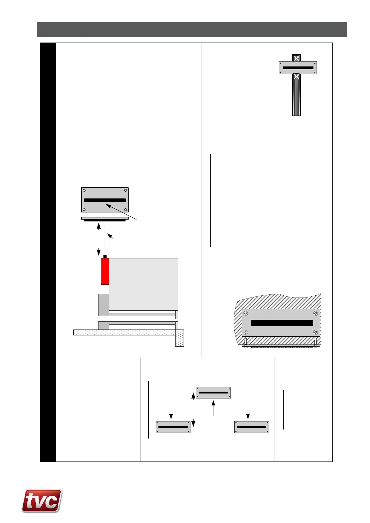
1) Mount the enclosure horizontally o n a fixed secure be d at a 9 0°Degree vertical and horizontal
angle from the magnetic door zone bracket. Ensur e the sensor is perp endicular to the magnets
surface.
3) Ensure the enclosure is secure ly fixed and d oes not shake or move during travel.
4) Ensure the magn etic sensor unit is within 10mm of the door magnets, and does n ot get closer than
5mm in distance.
5) Con nect the sign al cables as per con troller schematic drawing.
Sensor Head Unit Mounting Instructions
Magnet Mounting Instructions
Uni-Strut Fixing Method.
1) Fit the uni-strut to the sh aft guides in the usual way, within do or zone.
2) Move th e car to floor level, Align the Mag netic Door Zo ne Bracket with the uni-strut
so that the magn etic sensor is about 10mm away from the Magnetic Door Zone Bracket.
3) Fix the bracket to the uni-strut using usual guide clips, which can retain 3mm thick brackets.
Place the Magnetic tape back onto the bracket.
4) Align the Magnetic strip on the ver tical and hori zon tal centres of the tape.
Brick or
Concrete
Wall Fixing Method.
1) Move th e car to floor level.
2) Place the Magne tic Door Zone Bra cket against the wall with the magne tic sensor head about 10mm away central to the Magnetic Door
Zone Bracket, Mark the fixings, remove, drill and fix bracket to wall using standard Rawl plugs and self-tapping fixing screws.
3) Place magnetic strip onto bracket and align.
The Magnetic Door Zones can be fixed in many different ways depending on your appli cation.
The magnets can be attached directly to architrave or guide rails or the door zone bracket provide d. After final adjustment, the magnets can
be perman ently secured using super glue.
With the magnetic sensor unit fitte d, the mou nti ng options are as follows:-
Usin g the magnet only:- Architrave or Guide Rail.
Usin g mag net with mounting bracket:- Wall Mounted or Uni-Strut Mounted.
Magnetic
Sensor Unit
LIFT CAR
Door
Operator
Car at Floor Level
Side View
Front View
Magnet on bracket
Floor Level aligned to
centre of magnet
15 to 20mm
Front / Rear Zones
Floor 3
DZF Magnet
Front Door
Zone
Maintenance
Keep mag nets and sensors away from any
stro ng magnetic / electrical fields or loose magnetic
material such as swarf or filing s.
TVC Spare Parts
Magne tic Sensor:- 083 .000213
Full Unit:- 600 .340173.3
Bracket Assembly:- 200 .340051.3
Floor 2
DZR Magnet
Rear Door
Zone
Floor 1
DZF Magnet
Front Door
Zone
The magnetic door zone unit can be mounted on either the car o r
the sling.
When mounted on the car, levelling may be effected by u neven
car loading an d compre ssion of the car isola tion mountings. If this
is anticipa ted, we recommend the magnetic unit is mounted on
the front of the car where it will more accurately represent the ca r
sill position.
Alterna tively the unit can be moun ted on the crosshea d o r sling.
When mounting on the sling, check that any excess movement of
the sling in the guide s (due to wear or adjustment) does not
cause the magnetic sensor to become out of alignment with the
target.
min. 100mm
separat ion