Do you have a question about the TVLogic LVM-170W (G) and is the answer not in the manual?
Essential safety guidelines for using the monitor, including voltage, liquid spills, ventilation, and cleaning.
Details equipment compliance with FCC limits for digital devices in commercial environments.
Instructions for proper disposal of electronic equipment according to EU regulations.
Supports diverse SDI signals (480i, 720p, 1080i/p) and analog signals (Composite, S-Video, Component, RGB).
Features an all-in-one system, wide screen compatibility, DC/AC power, remote control, and built-in DVI.
Includes wide viewing angle, reclocked SDI OUT, VESA mounting, contrast ratios, brightness, OSD, and rack mountability.
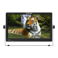
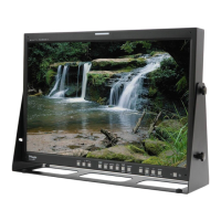
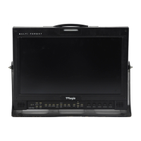
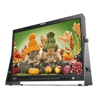
Labels and identifies functions of front panel buttons like ANALOG INPUT, SDI INPUT SELECT, and STAND BY.
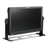
Details rear panel connectors including REMOTE, DVI-IN, CVBS, SDI inputs/outputs, and AC IN.
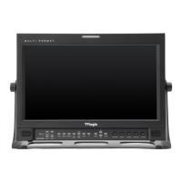
Labels and identifies functions of front panel buttons like ANALOG INPUT, SDI INPUT SELECT, and STAND BY.
Details rear panel connectors including REMOTE, DVI-IN, CVBS, SDI inputs/outputs, and AC IN.
Labels and identifies functions of front panel buttons like ANALOG INPUT, SDI INPUT SELECT, and STAND BY.
Details rear panel connectors including REMOTE, DVI-IN, CVBS, SDI inputs/outputs, DC 24V, and AC IN.
Selects desired ANALOG INPUT via a sub-menu for connected inputs.
Used to select between SDI INPUT A or B.
Transfers from OVER SCAN mode to UNDER SCAN mode for SD 1:1 SCAN.
Changes the monitor ratio on SD signal mode to 16:9.
Shows MARKER on screen; type selected via main menu.
Observes horizontal and vertical sync simultaneously.
Removes R/G for blue signal or switches to MONO mode using luminance value.
Adjusts CHROMINANCE and PHASE values.
Describes MENU, DOWN/BRIGHT, UP/CONTRAST, and ENTER buttons for OSD navigation.
Explains STANDBY indicator (RED/GREEN) and TALLY LED status.
RJ-45 port for connecting remote control devices.
DVI-I IN for DVI mode and FACTORY PGM for firmware updates.
CVBS1, CVBS2, CVBS3 terminals for Composite, S-Video, Component, and RGB signals.
Terminals for SDI-IN A/B and SDI-OUT A/B signals.
AC IN (100V-240V) and DC 24V IN for power supply.
Details mapping of Composite, Component, and S-Video signals to CVBS connectors.
Warning regarding the sequence of connecting power and signal inputs for proper operation.
Overview of the product's OSD menu organization, displaying PICTURE 1/2 and PICTURE 2/2.
Explains control using MENU, UP/DOWN, and ENTER buttons on the monitor.
Step-by-step guide for activating, navigating, and selecting OSD menu items.
Controls BRIGHT (degree of brightness) and CONTRAST (contrast ratio) within specified ranges.
Adjusts saturation (CHROMA) and tone (PHASE), with PHASE usable in analog modes.
Controls picture sharpness (APERTURE) and sets IRE value in NTSC mode.
Selects input SDI format (single/dual) and sampling mode (YCbCr/RGB).
Enables the filter for smoother transitions between colors.
Adjusts COLOR TEMP, GAIN RED, GAIN GREEN, and GAIN BLUE values.
Adjusts black level for red (BIAS RED), green (BIAS GREEN), and blue (BIAS BLUE).
Copies parameters from basic color temperature settings.
Controls marker type, center marker, safety area, and marker color.
Controls horizontal (H1/H2) and vertical (V1/V2) marker positions.
Details the REMOTE terminal and pin assignments for remote control functions.
Assigns functions to REMOTE pins (1-6) and POWER ON/OFF (PIN 7).
Introduces SYSTEM 1/2 and SYSTEM 2/2 menus for monitor configuration.
Resets BRIGHT, CONTRAST, PHASE, and CHROMA to their default values.
Controls LCD brightness (BACK LIGHT) and embedded audio volume/channel.
Details LOCK NUMBER, LOCK ENABLE, and BOARD VER information.
Configures OSD display time/position and source ID display/character/position.
Guides usage of ANALOG mode and input signal selection via the menu.
Explains how to switch between UNDER SCAN and SD 1:1 SCAN modes.
Lists supported resolutions and frequencies for DVI-ANA input.
Lists supported resolutions and frequencies for DVI-DIG Graphic mode.
Lists supported input signals for DVI-DIG Video mode.
Steps to enable DUAL LINK mode by selecting signal format in the picture menu.
Details input/output connectors and supported signal formats.
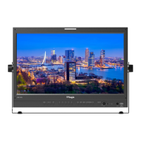
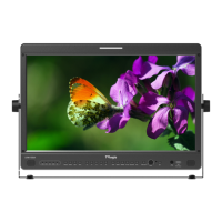
Lists LCD size, resolution, dot pitch, color depth, viewing angle, luminance, contrast, and display area.
Specifies audio output, power consumption, operating/storage temperatures.
Provides main body dimensions, weight, and included accessories.
Details input/output connectors and supported signal formats.
Lists LCD size, resolution, dot pitch, color depth, viewing angle, luminance, contrast, and display area.
Specifies audio output, power consumption, operating/storage temperatures.
Provides main body dimensions, weight, and included accessories.
Accessory for monitor protection and handling.
Accessory for attaching the monitor to a tripod.
Protective case for transporting the monitor.
Mounting accessory for compatibility with V-mount systems.
Accessory for installing monitors into standard equipment racks.