/ 11 /
The 850EMT can be connected to MX detectors or
ancillary devices using the tool base, the Ancillary lead,
or infrared communications.
4.3 Connecting to an
MX Device
IR Link
The IR mode needs to be enabled at the re
panel before the IR link can be used.
CAUTION
Turn off the Sounders before enabling the IR
Mode, to avoid the devices from overloading
the loop and from being accidentally
activated by the 850EMT Address
Programming Tool.
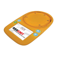
The 5 different modes used by the 850EMT to
communicate with the device are:
• IR High: The 850EMT communicates with the
detectors placed at a distance between 1m to 15m via
the infrared link. It is indicated by the icon on the
bottom left hand corner of the main screen.
• IR Low: The 850EMT communicates with the
detectors placed at a distance between 0 and 5m via
the infrared link. It is indicated by the icon .
See Section 4.6 for using IR mode.
• AUX Cable: Communication between the 850EMT and
the ancillary is possible by attaching the auxiliary cable
to the AUX socket of the 850EMT and plugging it on to
the auxiliary device (3 pins). Refer to 4.5 “Connecting
to an Ancillary Device” on page 13. It is indicated by
the icon on the main screen.
NOTICE
If the 850EMT is not in the Auto mode,
it cannot automatically detect the
Communication mode to be ‘AUX’ for legacy
ancillary leads. You have to manually select
‘AUX’.
Auto mode - Not Available
This functionality is not applicable for:
• The 813P and the 801F/801FEx Flame
detectors.
• Intrinsically Safe detectors such as the
801PHEx, 801HEx, 801CHEx etc.
These detectors can communicate with
the 850EMT via only the Tool base mode of
communication.
• Tool Base: Communication between the 850EMT and
the device is possible by placing the detector in the
lock position on the tool base of the 850EMT. Refer
to 4.4 “Connecting to a Detector” on page 12. It is
indicated by the icon .
• Auto: The 850EMT automatically detects the kind of
mode with which it has to communicate with the
device by considering each of the following scenarios:
– If the Ancillary lead is plugged in AUX Mode is
selected.
– If a detector is xed onto the tool base, the Tool
Base mode is chosen.
– If no auxiliary cable is present and the detector is
not xed onto the tool base, the 850EMT chooses IR
Low as the default mode of communication.
– If the ancillary is connected to the 850EMT
via the Auxiliary cable and a detector is xed on
the tool base, the 850EMT does not choose any
communication mode.
In this scenario, an error message is displayed as:
Setup not allowed
Remove detector or disconnect AUX cable. It is
indicated by the icon
This is due to a conict between the AUX mode and
the Tool base modes of communication.
 Loading...