/ 7 /
3 Operating Instructions
3.1 Indicators and Controls
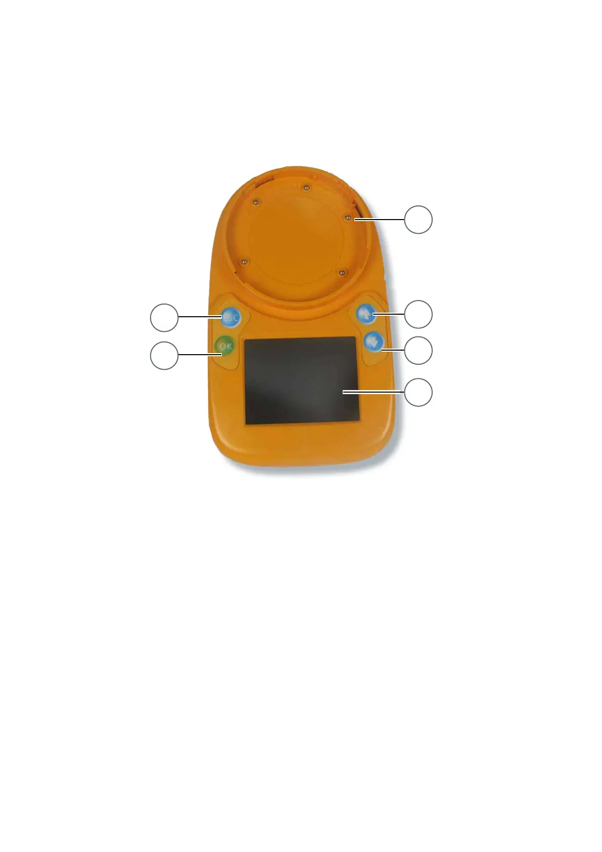
The 850EMT is shown in Figure 3. The numbered items in the gure are explained in the following paragraphs.
Fig. 3: 850 Engineering Management Tool
1 – Tool Base
2 – Escape Button
3 – OK Button
4 – Up Arrow Button
5 – Down Arrow Button
6 – LCD Display Screen
Tool Base
The circular area is used to t an MX detector, by rotating the detector in the clockwise direction until it reaches the
lock position. For additional details, see 4.4 “Connecting to a Detector” on page 12.
2
3
1
4
5
6
 Loading...