/ 14 /
• Address: Displays the address of the device. To change
the address of the device, press the Change Address
button. See Section 5.3
• Type: Displays the type of the device
• SKU: Shows the stock code of the device (for a
replacement)
• Point Text: Represents the point/area where the device
is located. Usually shows N/A
• Zone Label: Reflects the Zone where the device is
located. Usually shows N/A
• Dirtiness: This represents the percentage of dirt or
dust that is present inside the sensor, accumulated
over a period of time. This field cannot be altered. The
percentage value obtained may be different from the
value displayed for the ‘Dirtiness’ field on the panel
screen.
Device Status/Change Settings
Address: 128
Type: SYS800
SKU: 516.800.960
Point Text: Sounder-Beacon Device
Zone label: Bldg 2, Block A
Dirtiness: N/A
CH-1: 255
Change
Address
MOREHOLD
DOWNLOAD CONFIG
COMMISSIONING MODE
SERVICE MODE
REPORT GENERATOR
RETURN
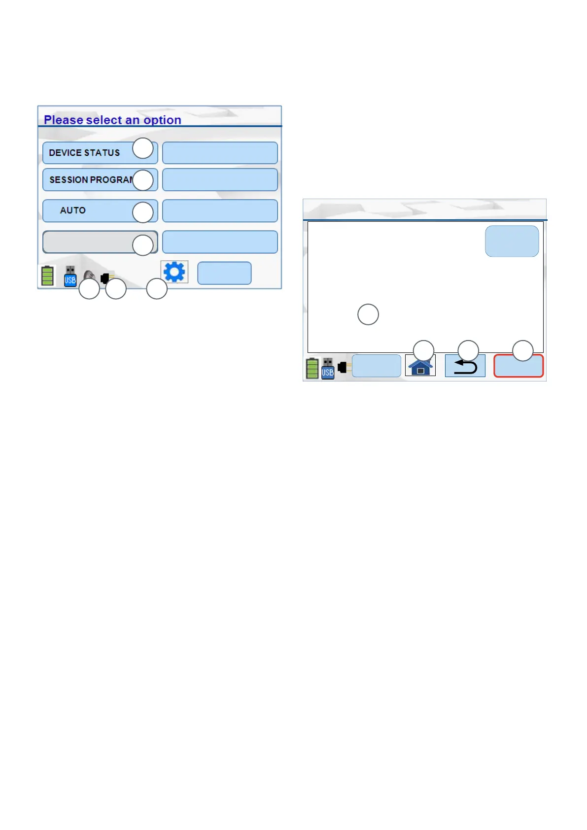
The Main screen is displayed as shown in
Figure 10.
The following sections detail the menu options.
The properties shown on this screen and the More
screen are as follows:
5 Menu Details
Fig. 10: Main Menu-Listed Options
1 – Device Status and Change Settings
2 – Session Program-Manual and Auto Modes
3 – Communication Mode (For this example shown as AUTO)
4 – Test Functions
5 – Detector connected to 850EMT
6 – Device connected via an Ancillary to the 850EMT
7 – Navigate to “850EMT Settings”
Fig. 11: Device Status & Change Settings Screen
1 – Channel analogue values
2 – Home Icon - Returns to the main screen
3 – Return Icon - Goes back to the previous screen
4 – Displaying more information
1
2 3 4
1
2
3
Use Device Status option to display the status/
congured settings of the device connected to the
850EMT.
An example Device Status screen is shown in Figure 11.
5.2 Device Status
5 6 7
TEST FUNCTIONS
4
5.1 Main Menu Options
There are ve options, as follows:
• DEVICE STATUS - used to display the previously
congured device settings and allows you to change
these settings as required. See 5.2 “Device Status” on
page 14.
• SESSION PROGRAM - allows the user to manually/
automatically programme addresses into the device
and reset the session table. See 5.4 “Session
Program” on page 16.
• COMMUNICATION MODE - pressing this changes
the device communication mode between IR High,
IR Low, Aux Cable, Tool Base and Auto. See 4.3
“Connection to a MX Device” on page 11.
• TEST FUNCTIONS - used to perform additional
commissioning tests on the device and alter the
default settings for Visual Alarm Devices. See 5.5 “Test
Functions” on page 17.
• 850EMT SETTINGS (cog wheel) - used to change the
850EMT settings. See 5.6 “850EMT Settings” on page
2 1.
 Loading...