20
CHAPTER 4. OPERATION FOR TRACTOR
4.1 Controls and Instruments
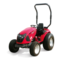
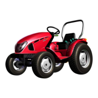
The controls and the instruments of the tractor are shown in Fig.4-1, Fig.4-2,Fig4-3
1. Preheating Starting switch 10 (Electricity lock)(Fig.4-2)
Insert key into the switch. Turn the key clockwise, the electrical equipment and battery are connected,
the preheating plug is preheated, then continue to turn it to the “start” position.
2. Front head light switch 23
Push the switch to the upside, the front head light(upper beam) is turned on, and its pilot lamp is
turned on ; (No.1) When in the neutral position, the front head light is turned off.
3. Steering light switch
Push the switch to the upside, the left steering light (is turned on,) and the left steering pilot lamp
in the gauge is turned on; Push the switch to the downside, the right steering light (is turned on,) and
the right steering pilot lamp is turned on; when in the neutral position, the steering light and steering
pilot lamp are turned off.
4. Hand throttle 26 (Fig.4-2)
Pull the hand throttle backward, the fuel flow will increase. While push it forward, fuel flow will
decrease.
5. Shut-off full rod 22 (Fig.4-2)
Pull rod backward, the engine will be stopped. Then push it forward to the original position.
6. Foot throttle 15 (Fig. 4-2)
Depress the pedal down, the fuel flow will increase : loosen it, the fuel flow will decrease .
7. Decompressing lever 12 (Fig. 4-2)
Turning the lever clockwise is for the decompressing position.
8. Main and sub-shifting levers 19,20 (Fig. 4-2)
The positions of main and sub-shifting levers are as shown in the mark carved in the top surface of
upper front cover of transmission housing. Shift the two levers into different positions respectively,
various forward and reverse speeds can be obtained. The neutral position is in the middle.
9. Clutch pedal 21(Fig. 4-2)
Depress the pedal, the release arm will touch stop screw, thus the clutch is disengaged.