48
5.14 Adjusting of Front Wheel Deflection Angle and Toe-in
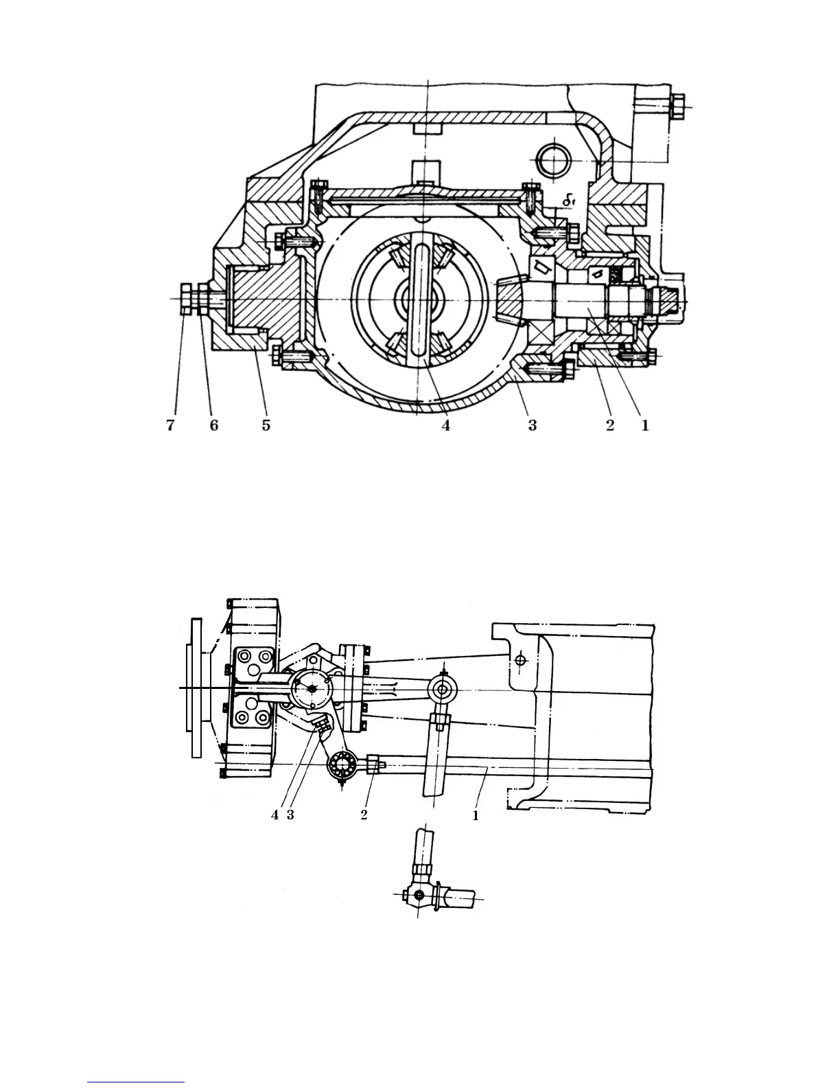
Fig. 5-19 Front central drive ass’y
1. Front central drive gear ass’y 2. Rear support 3. Central drive case 4. Differential ass’y
5.Front support 6. Lock nut 7. Adjusting bolt
Fig. 5-20 Steering mechanism assy
1. Cross-rod 2. Lock nut M8X1.5 (L.H) 3. Adjusting bolt 4. Lock nut M10