37
In case of abnormal teeth contact condition, it is possible to make adjustments according to Fig. 5-4.
The solid line with arrow head shows the adjustment of teeth contact, while the dashed line shows the
adjustment of backlash.
(4) When it is assured of normal teeth contact condition, the backlash could be adjusted to 0.1~0.2 mm.
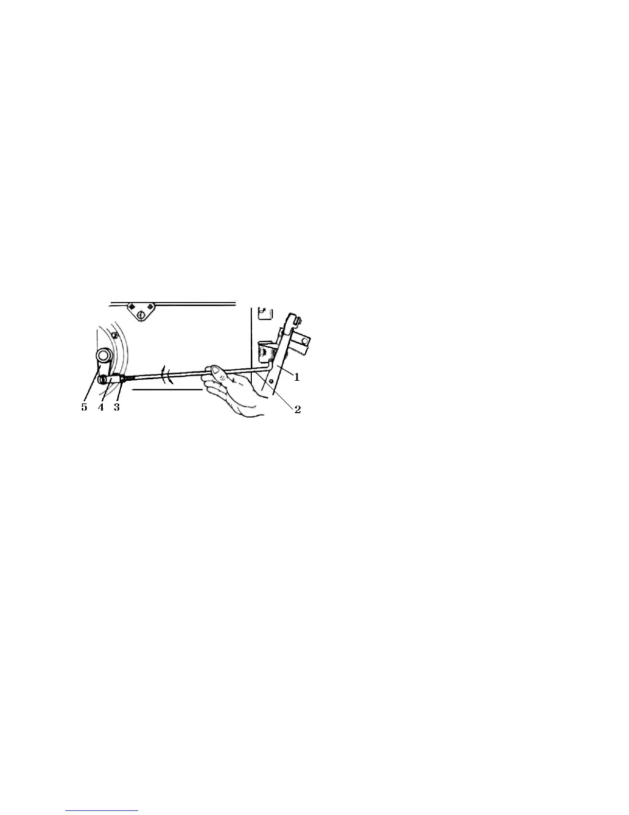
5.4 Adjustment of Brakes
The adjustment of the brakes is shown in Fig. 5-5. The length of the control rod is adjusted so that
when the top of the brake pedal is subjected to a force of 13 N. the travel should be 20~40 mm.
It shall be assured also that the left and right brakes will work equally effectively.
Fig. 5-5 Adjustment of brakes
1. Brake pedal
2. Control rod
3. Lock nut
4. Adjusting fork
5. Rocker arm of cam
5.5 Adjustment of Final Drive
For adjustment of preloading of the drive shaft bearings, see Fig. 5-6
(1) Place of piece of fuse wire of about 2mm diameter between the inner bearing cover and the bearing
No.7307. Place also a set of adjusting shims of a total thickness of about 1.5 mm. After mounting the
inner bearing cover, tighten the bolts with a torque of 40~50 N*m, to press the fuse into a flat plate.
(2) Dismount the bearing cover, take out the fuse plate and measure its thickness.
(3) Deduct the thickness of the fuse plate from the total thickness of the shims. This will form a set
of shims, the use of which will result in clearance or interference of less than 0.1 mm. Assemble the
shims and bearing cover and tighten the bolts with a torque of 40~50 N*m.