43
1. Draft control handle 2.Sector plate 3. Link arm 4. Lock nut 5. Lift arm
6. Push rod of the draft control system 7. Spring rod 8. Dowel rod
9. Spring assembly of draft control 10. Rocker arm of upper hitch point 11. Lift housing
12. Inner lift arm 13. Pull spring 14. Draft control lever 15. Main control valve
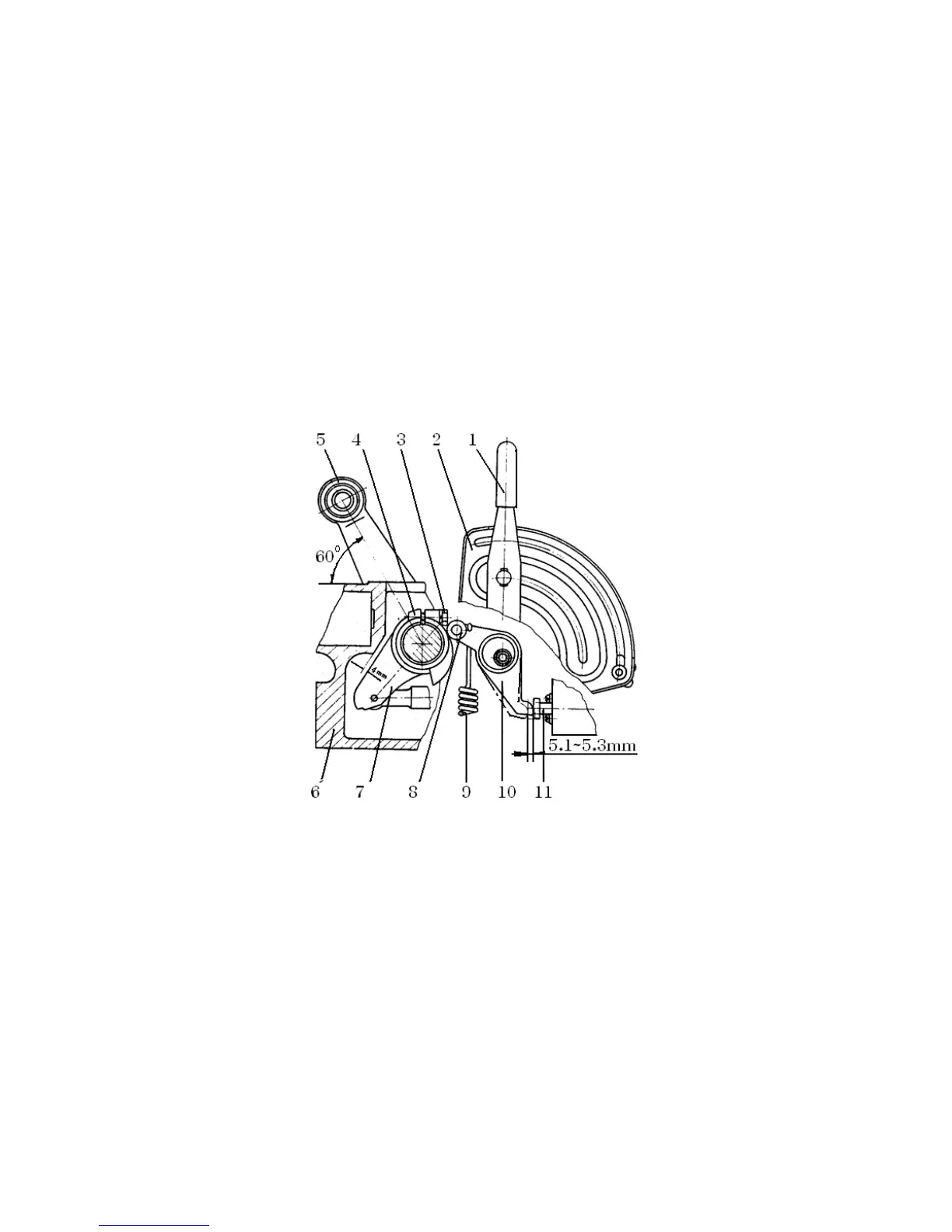
(3) For adjustment of position control cam, please see Fig. 5-13
Put the handles of the position, and draft control in the vertical position. Make the lift arm an angle of
60° with horizontal plane and make the inner lift arm have a clearance of 4mm with the housing.
The position control cam is so turned that the control end of the position control lever push the main
control valve 5.1+0.2mm into its block from its outmost position. Then tighten the belt on the position
control cam.
Fig. 5-13 Adjustment of the cam of position control
1. Position control handle 2. Sector plate for position control 3. Bolt 4. Cam for position control
5. Lift arm 6. Lift housing 7. Inner lift arm 8. Roller 9. Pull spring 10. Position control lever
11. Main control lever
5.10 The Operation Controls of Front Drive Axle
The separating and joint of front drive axle of 4 wheel drive tractors are controlled by the handle under
the left side of drivers seat. See Fig. 5-14 No.4. Put the handle backward, it shuts together the front
drive axle, other wise if takes off them.