42
5.9 Adjustment of the Lifter
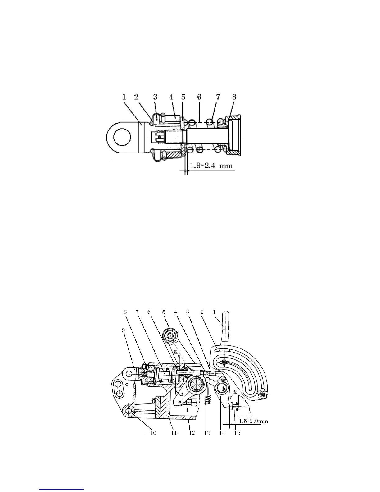
(1) For the adjustment of spring assembly of draft control system, see Fig. 5-11.
After the spring assembly is put together, the clearance between the washer and the shoulder of the
spring rod should be 1.8~2.4 mm
Fig. 5-11 Adjustment of draft control spring assembly
1. Upper link connector 2. Dustproof cover 3. Pin 4. Nut 5. Washer of draft control spring
6. Spring rod 7. Draft control spring 8. Spring seat
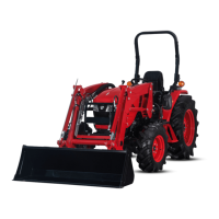
(2) For the adjustment of push rod of the draft control system, please see Fig. 5-12. Put the draft
control spring assemble into the lift housing, make its front end to contact surface E of the housing,
and insert the locating pin.
Put the draft and position control handles in the vertical position, adjust the length of the push rod, and
make sure that its end will contact the surface A of the spring rod. At same time, make the control end
G of the draft control lever have a clearance of 1.5~2 mm with the end surface of the main control \
valve at moment the main control valve in outmost position.
Fig. 5-12 The adjustment of the push rod of the draft control system