C099-F9P - User Guide
UBX-18055649 - R02 Using the C099-F9P Page 14 of 48
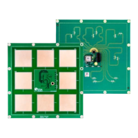
Figure 11: Battery charge status LED
4.2 GNSS RF input
The C099-F9P board should be used with the antenna supplied with the kit. If another active antenna
is used, be aware that the RF input has a bias output designed to supply 3.3V DC with a 70 mA
maximum current load. A DC block is advisable if the board is connected to a signal distribution
scheme or GNSS simulator to prevent any potential shorting of the antenna bias.
Figure 12: GNSS antenna connector
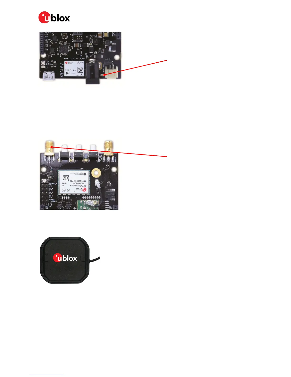
When using the supplied antenna it is advisable to use the ground plane provided. Otherwise ensure
that there is an adequate ground plane, e.g. by mounting in the center of a metallic car roof.
Figure 13: The supplied GNSS multi-band antenna
4.3 User interfaces
The C099-F9P has a number of fixed connection options besides the wireless modes. There is also an
additional Arduino R3 / Uno interface for external host connection.
The USB connector on the board provides connection via an on-board hub providing:
Red battery charge LED
SMA GNSS antenna connector

 Loading...