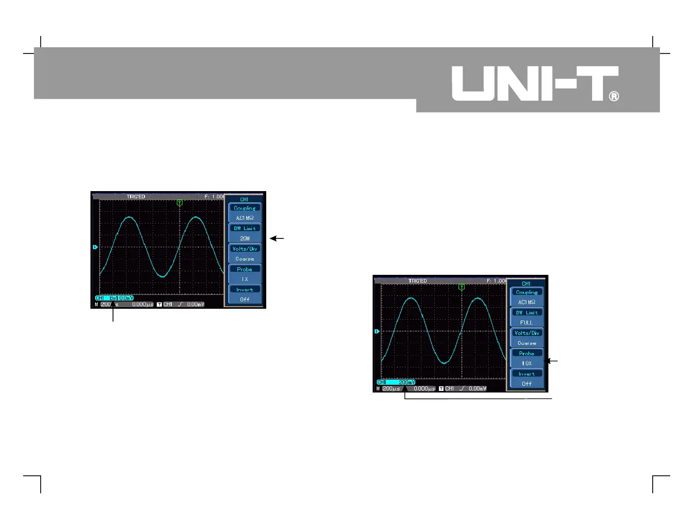
Press [ ] then [ ]. The noise and high frequency
quantities over 20MHz of the signal being tested are
now restricted. Waveform display is as follows.
3. Setting up the probe rate
To match the probe attenuation factor setup, it is
necessary to set up the probe attenuation factor in
the channel operation menu accordingly For
example when the probe attenuation factor is
10:1 set the probe attenuation factor at 10X in
the channel menu Apply this principle to other
values to ensure the voltage reading is correct
The figure below shows the setup and vertical
range display when the probe is set at 10:1.
Figure 2-5 Waveform display when bandwidth
Figure 2-6 Setting the probe attenuation factor in the
 Loading...
